This thread has been locked.

If you have a related question, please click the "Ask a related question" button in the top right corner. The newly created question will be automatically linked to this question.

LM317L: What is the current limit torlerence?

Part Number: LM317L
Other Parts Discussed in Thread: TPS2553, LM317

Dear Sir,

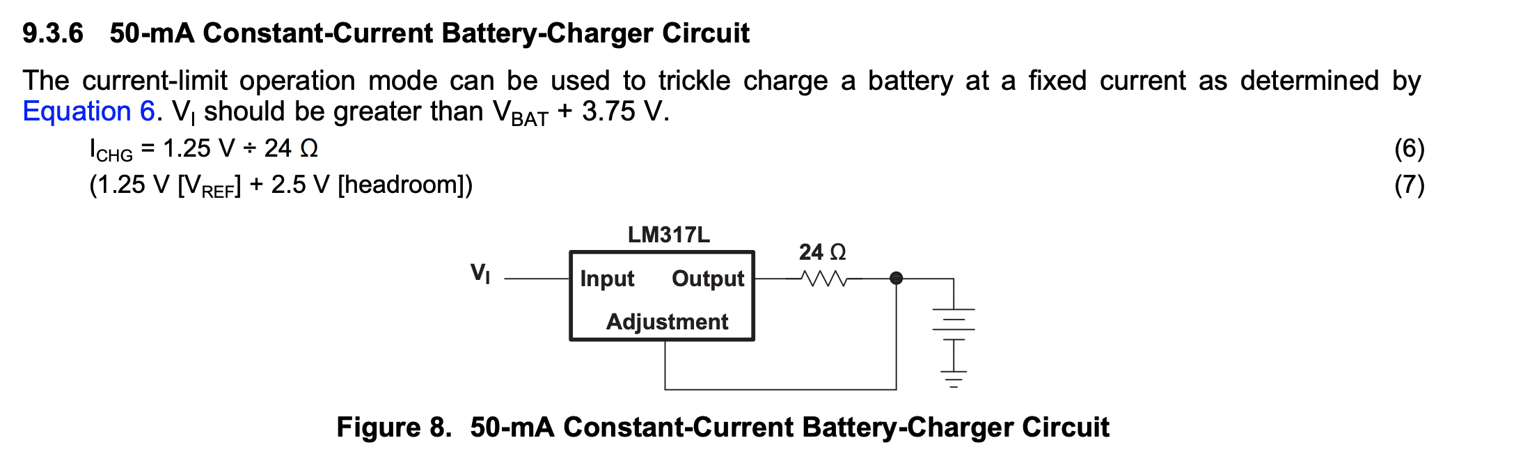
Please check the datasheet page 12 "9.3.6 50-mA Constant-Current Battery-Charger Circuit".

I want to use the current regulator to limit the input current.

My resistor torlerence is 1% so that what is max. current torlerence on the application circuit??

PS: My goal is 25mA, R=50ohm.

 , http://www.ti.com/lit/ds/symlink/lm317l.pdf

  • Hi Gordon,

    The LM317L's current limit is more a function of thermal self-protection. It will fold-back the current based on the thermal conditions to protect itself:

    So the accuracy of the current for the below circuit:

    is dependant on the accuracy of the reference: Which could range from 1.2 to 1.3V. So 24-26mA is the current range that can be expected (ignoring the tolerance of the resistor. Please note: the LM317L will not stop charging based on voltage and figure 8 says that VIN should be VBAT+3.75V. Since this device was introduced to the market in 1976, I imagine the target battery chemistry was Nickel Cadmium or Nickel Metal Hydride. Li-ion cells were not generally available until after 1991

    I hope this answers your question. 

  • Dear Sir,

    How much temperature enable the thermal protect?

    And I find out the current regulator beahiver is differnt the general current limiter( TPS2553).

    TPS2553 change Vout status is very quickly when I change the electrical load.

    The LM317L is very slow and max current feed back to 16.5mA. Do you know why??

    LM317 R=47ohm / measure result:

    TPS2553 measure result:


  • Hi Gordon,

    The images you posted are not showing. That being said, what I imagine you are seeing is the key difference between an E-Fuse or load switch and an LDO.

    The TPS2553 only focuses on limiting the current into the load. 

    The LM317L only focuses on regulating the output voltage for the load. 

    While the actual temperature to thermal protect is not listed, since TJ is rated operationally up to 125C, I suspect that the thermal limit is somewhere around 140C to 170C. Now, what current will this kick in? It is a strong function of which package you are using. See the table below:

    so the PK or SOT-233 package has the lowest RTJA ar 51.5C/W and the PW or TSSOP-8 package has the worst at 149.4C/W.

    To use this, the power dissipation will in (VIN-VOUT)*ILOAD is the power in Watts that the LM317L is dissipating.

    The power in Watts (W) times the RTJA shows a theoretical junction temperature rise above the PCB ambient. 

    So the full equation is (VIN-VOUT)*ILOAD*RTJA+TA. Where

    VIN is the input voltage for the LM317L

    VOUT is the output voltage (~1.25V+ILOAD*R+VCELL

    ILOAD is the targeting load current

    RTJA is from the table above

    and TA is the ambient temperature of the PCB

    I hope this helps (again sorry I can't see the images you uploaded).

    Regards,