This thread has been locked.

If you have a related question, please click the "Ask a related question" button in the top right corner. The newly created question will be automatically linked to this question.

TPS92513HV: Soft start TPS92513HV

Part Number: TPS92513HV
Other Parts Discussed in Thread: TPS92515, TPS92513

Hello,

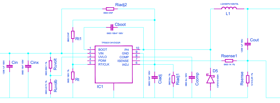
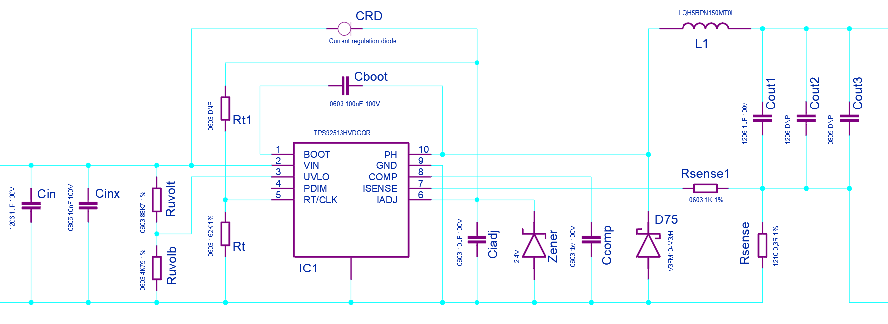
We would like to use the TPS92513HV driver with a soft start function (for example 300-500ms).

I cannot find anything about soft start in the datasheet. Is there a way to use the PDIM of IADJ input to achieve this behavior?

Thanks in advance, Cees

  • Hello Cees,

    The behavior during turn on may not be what you desire since the compensation capacitor needs to charge to get to regulation.  You can try PWM to and RC filter sent to iadj to see how it behaves.  You can also try sending PWM to the pwm pin starting at low duty cycle instead of using iadj.  You may see no light for a while until comp charges to regulation.  Hysteretic parts such as the TPS92515 are better suited for this since they regulate peak current without a compensation capacitor so the respond instantly.  If there is output capacitance across the LEDs you will also get a delay charging the output capacitor since the current starts out very low.  Best is to try it for your application and see if it is what you are trying to do.

    If it is not doing quite what you are looking for you can reduce the comp capacitor value, from the datasheet:

    "8.3.6 External Compensation (COMP Pin)
    The TPS92513 error amplifier output is connected to the COMP pin. The TPS92513 is a simple device to
    stabilize and only requires a capacitor from the COMP pin to ground (CCOMP). A 0.1 μF capacitor is
    recommended and will work well for most all applications. If an application requires faster response to input
    voltage transients, a capacitor as small as 0.01 μF will work for most applications if needed. The overall system
    bandwidth can be approximated using Equation 9."

    From the datasheet:

    "The IADJ pin voltage range is 0 V to 1.8 V and is internally clamped at 1.8 V. If analog current adjustment will
    not be used, the IADJ pin can be connected to VIN through a resistor for a default ISENSE voltage of 300 mV.
    This resistor should be sized so that the current into the IADJ pin is limited to 100 μA or less at the maximum
    input voltage. A precision reference between 0 V and 1.8 V can also be used on IADJ to control the ISENSE
    voltage. If no external voltage source is available, the IADJ pin can be tied to the RT/CLK pin either directly or
    using a resistor divider to generate a voltage between 0 V and 500 mV. If a resistor divider is used off the
    RT/CLK pin to generate the IADJ voltage it will introduce a parallel resistance with the RT resistor. High value
    resistors are recommended in that case and the parallel combination must be used to calculate the switching
    frequency. The current sense voltage is most accurate with IADJ voltages between 180 mV and 1.8 V for a
    dimming range of 10:1. Below 180 mV the TPS92513 dims well but may have more variation between circuits.
    Due to internal offsets pulling IADJ to 0 V will not result in a current sense voltage of 0 V. Some small current will
    continue to run unless the PDIM pin is pulled low or the device is disabled using the UVLO pin. Analog dimming

    is also most accurate when the device is in continuous conduction mode (CCM). If the highest accuracy possible
    is desired during analog dimming, size the inductor so that 1/2 the peak-to-peak inductor ripple is less than the
    minimum LED current to remain in CCM. The IADJ pin should be decoupled with a 10 nF capacitor to ground. A
    1 kΩ resistor should be used between the ISENSE pin and RISENSE to protect the pin in the event RISENSE opens
    or there is a transient due to one or more LEDs shorting."

    Best Regards,

  • Hello Cees,

    I haven’t heard back from you, I’m assuming you were able to resolve your issue.
    If not, just post a reply below (or create a new thread if the thread has locked due to time-out)

    Best Regards,

  • Dear Irwin,

    Thanks for your support.

    We want to test this option: 'You can try PWM to and RC filter sent to iadj to see how it behaves.'

    See attached schematic as it is now. Do you mean to make an RC filter with Ciadj and Riadj1?In this case we will not place Riadj2 and Rt1. So without using the PWM input.

    Can you advise if  this is correct and which values we can start with for Ciadj and Riadj1?

    Thanks in advance,

  • Hello Cees,

    I cannot calculate your values without know more information such as Vin, Vin range.  You can calculate your RC values fairly easily.

    The iadj pin when pulled high to 2.77V can sink 100 uA (this will set the minimum upper resistor value if you choose to use it this way).  If you use both Riadj1 and Riadj2 you can set the divider to charge to a known value below 2.77V (3V is the absolute maximum of the iadj pin)  The voltage from low to high current will be 0-1.8V.  This is an RC calculation, you can calculate this or simulate it because it will behave different depending on the values chosen.  The power down reset time will depend on how you implement this.  A single resistor, Riadj2, and using the 100 uA maximum sink current will make the ramp more linear but it will also cause the reset time to be longer since it has to discharge through Riadj2 when it is off.  If your resistor values are high there is a current sink (iadj clamp) you have to take into account, 1 uA at 1.8V on iadj.  The Ciadj capacitor will need to be much larger for your time constant.  For example using 10 uA charging current and 500 mS the capacitor value would need to be 2.8 uF.  Using PWM to an RC to the iadj pin will reduce this capacitor value down dependent on PWM frequency.

    The power up may not behave the way you expect, this part was not meant to start this way.  A hysteretic part such as the TPS92515 would be better suited to do this.  Rt1 shouldn't be used this way, the RT pin is for setting switching frequency and cannot pull up on Iadj.

    "The IADJ pin voltage range is 0 V to 1.8 V and is internally clamped at 1.8 V. If analog current adjustment will
    not be used, the IADJ pin can be connected to VIN through a resistor for a default ISENSE voltage of 300 mV.
    This resistor should be sized so that the current into the IADJ pin is limited to 100 μA or less at the maximum
    input voltage. A precision reference between 0 V and 1.8 V can also be used on IADJ to control the ISENSE
    voltage. If no external voltage source is available, the IADJ pin can be tied to the RT/CLK pin either directly or
    using a resistor divider to generate a voltage between 0 V and 500 mV. If a resistor divider is used off the
    RT/CLK pin to generate the IADJ voltage it will introduce a parallel resistance with the RT resistor. High value
    resistors are recommended in that case and the parallel combination must be used to calculate the switching
    frequency. The current sense voltage is most accurate with IADJ voltages between 180 mV and 1.8 V for a
    dimming range of 10:1. Below 180 mV the TPS92513 dims well but may have more variation between circuits.
    Due to internal offsets pulling IADJ to 0 V will not result in a current sense voltage of 0 V. Some small current will
    continue to run unless the PDIM pin is pulled low or the device is disabled using the UVLO pin."

    Best Regards,

  • Hello Cees,

    I haven’t heard back from you, I’m assuming you were able to resolve your issue.
    If not, just post a reply below (or create a new thread if the thread has locked due to time-out)

    Best Regards,

  • Hello Irwin,

    The Vin working range will be 24-48Vdc. But there might be accidental fluctuations to 55Vdc. Due to this wide input range and the 3V absolute maximum for IADJ it's not possible to use a fixed voltage divider.

    We think about using a 2,4V Zener diode instead of Riadj1 and a current regulation diode (CRD) instead of Riadj2.Then it would be possible to charge Ciadj with any supply voltage and clamp IADJ at a maximum of 2,4V regardless high fluctuations on the supply.

    See schematic below.

    Please let me know your thoughts on this idea? Do you see any problems with such solution?

    Thanks in advance, Cees

  • Hello Cees,

    The Iadj pin can be pulled above that voltage if the current is below 100 uA.  This means at 55V you can use 520 Kohm as the pull up on the RC or higher.  The value can be even when calculating with the bottom resistor of the divider.

    Try 499 Kohm for the top resistor and 56.2 Kohm for the bottom, or something like that with a 4.7 uF capacitor or the10 uF you already have on the board to Iadj to see how it works.

    Worst case current to Iadj in this case would be (55V - 3V)/499 Kohm - 3V/56.2 Kohm = 51 uA, well under 100 uA.

    A current regulator diode is not common or inexpensive.  It can also be created with discrete parts.  If the variance in turn on time with respect to input voltage is not desirable a separate resistor/zener can provide a fixed voltage to base the RC on.

    Best Regards,

  • Hello Cees,

    I haven’t heard back from you, I’m assuming you were able to resolve your issue.
    If not, just post a reply below (or create a new thread if the thread has locked due to time-out)

    Best Regards,