This thread has been locked.

If you have a related question, please click the "Ask a related question" button in the top right corner. The newly created question will be automatically linked to this question.

LP5907: Spur at Cold Temperature

Part Number: LP5907

Hi Expert,

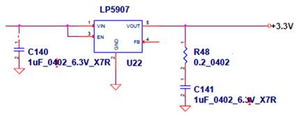
We observe ~35dBc spur at +/-4Mhz offset under -35degC. We tried to touch the chip with hand, the spurs would disappear. In addition, we also found if adding another Cout=4.7uF, the spur would disappear too.

Could you please clarify is it related to the temperature or output cap in terms of stability?

Thanks.

Allan

  • Hi Allan, 

    In addition to the 4MHz spur you observed at 4MHz, have you seen any failure or performance degrading related to this spur? In order to confirm if the ESR resistor and the output capacitor are causing the problem at cold temperature, will you provide me the complete part number for them or datasheet that shows their performance at cold temperatures? 

    Regards, 
    Jason Song

  • Dear Jason,

    Yes, this spurious will degrade system performance. The part number is GRM155R70J105KA12. The manufacture is MARATA. Please refer attached file for datasheet.

    GRM155R70J105KA12_MURATA_20160308.pdf

    Tony

  • Hi Tony, 

    Will you provide the scope-shot of the output that shows the ringing due to the spur at 4MHz? Other than the LDO, can you identify any other source that may generate the 4MHz signal? Have you tried to identify the source for the spur?

    Regards, 
    Jason Song

  • Hello Allan,

    I would be happy to help Jason assist you with this question.
    Can you identify the load current during these tests?

    Can you confirm that when the 4MHz spike is seen, only the 0.2 ohm resistor in series with the 1uF cap is seen on the load?
    That is, no additional capacitors or other filtering components (inductors, ferrite beads, etc)?

    Thanks,

    - Stephen

  • Dear Jason,

    4MHz oscillation is gone when we on purpose warm up the LDO. So we think 4MHz oscillation comes from LDO. We learned the information from TI E2E™ library. The phase margin is ~28deg at cold if output capacitor is 1uF only. And phase margin will be increased if we increase capacitoance. Based on this information, we add one more 4.7uF parallel to 1uF. Then 4MHz oscillation is gone. Does this change make sense?

    Tony

  • Hi Tony,

    The 1uF capacitor your customer has chosen places the device into an unstable mode of operation.

    The 1uF is rated for 6.3V but has a voltage bias of 3.3V.
    Ceramic capacitors lose a lot of capacitance just due to voltage bias alone.
    An X7R, 0402, 6.3V rated 1uF ceramic capacitor on AVX's website shows a 35% loss in capacitance with 3.3V applied.
    Click the DC Bias tab in the following link from AVX's SpiCat tool.

    spicat.avx.com/.../04026C105KAT2A

    So your 1uF cap is down to 0.65uF without considering tolerance (10% or 20%), and other tolerances shown in the datasheet.

    When you change it to a 4.7uF cap, you increase the effective capacitance to meet the stability requirements in the datasheet.

    Thanks,

    - Stephen

  •  Dear Stephen,

    Thanks for your valuable comment. We will use 4.7uF as our solution.

    Regards,

    Tony

  • I'm glad I could help Tony.

    Let us know if you have any additional questions.

    Thanks,

    - Stephen