This thread has been locked.

If you have a related question, please click the "Ask a related question" button in the top right corner. The newly created question will be automatically linked to this question.

UCC28704: Design validation of a 5V/1A Universal AC/DC

Part Number: UCC28704

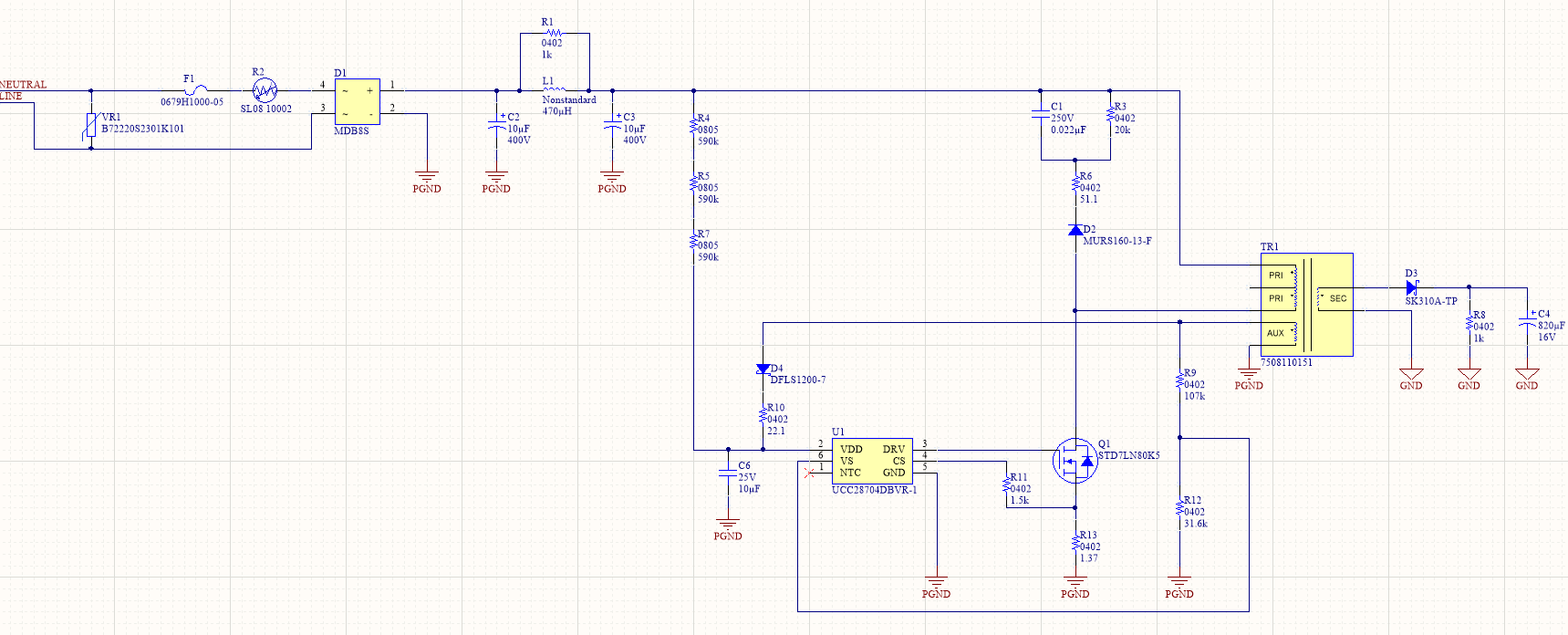
We're developing a Universal AC/DC 5V/1A using the UCC28704, that was based on the WeBench Design Tool. We houve some doubts about the circuit, since we're using the 7508110151 transformer from Wurth, but can't seem to find any reference from it on the WeBench, will our circuit function correctly using these components ?

We will also need to supply some non-isolated components, which will require approximately 3V3/20mA. Is it possible to use the auxiliary winding with a low quiescent LDO ? If so, whre is the best place to connect it ?

Best Regards, Drauzio.

  • Hello Drauzio,

    Thank you for your interest in the UCC28704 PSR flyback controller.

    I found the transformer specification by a web search on that number.  As far as I can tell, it is entirely suitable for your 5V/1A off-line application.

    On the other hand, your wish use add another non-isolated output may present some problems.  Although the LDO output load is about 66mW, the only winding available to draw from is the AUX winding and that supplies about 15V to VDD.  Total additional load is about 300mW.  This really impacts your no-load stand-by power, if you are required to meet such a specification.

    The LDO can't be connected to VDD because it would load down VDD and prevent the UCC28704 from reaching ~21V to start up. You can add another rectifying diode and filter cap to AUX (like D4 and C6) to provide a separate VDD2 which would not interfere with start-up.

    Since the UCC28704 works with Primary-Side Regulation (PSR), it regulates the output indirectly by sampling the reflected output voltage on the AUX winding at the end of the flyback time.  Normally the loading on AUX is extremely low and its voltage reflects the output.  But if you add another load on it that is higher than the output load, then that rail will be the one that is regulated and the output will drift higher, uncontrolled.  A separate VDD2 rail will only work if you have a minimum load on the Secondary VOUT that is higher load than any of the loads on the primary side. 

    You can reduce the minimum output load if you modify the transformer and add a tap the AUX or another winding with fewer turns to reduce the VDD2 rail voltage. For example, the transformer 7508110151 has 7 turns on the secondary and 22 turns on the AUX.  If you add a tap at 6 turns (or 5, or 7), depending on the LDO overhead, you can reduce the required output minimum load to less than100mW.   It is much reduced, but still affects stand-by power. 

    Regards,
    Ulrich