This thread has been locked.

If you have a related question, please click the "Ask a related question" button in the top right corner. The newly created question will be automatically linked to this question.

BQ40Z80: How to connect to PDSG PFET when pin20 is used as PDSG

Part Number: BQ40Z80
Other Parts Discussed in Thread: BQSTUDIO

In the design, I want to use pin20 as PDSG function, and TRM(SLUUBT5A) is described as follows in Chapter 11.1:

"The exception is if the PDSG functionality is selected using the LEDCNTLA pin(RL0, pin20),which has an internal high-voltage drive capability and can drive the PFET gate directly(in which case the polarity of the pin signal changes)."

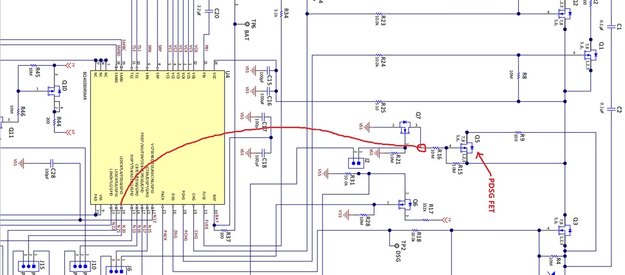
Does this mean that pin20 is directly connected to the grid of PDSG PFET as shown in the figure below?

If what I said is wrong, please tell me the correct connection method, thank you!

  • Hello Changhe,

    NO, pin 20 connects to J2 pin1. Pin 20 is active high, so it turns on the NMOS Q7, which in turn turns on the PMOS Q5.

  • Hello Damian,

    I understand that if other pins are used as PDSG, Q5 is driven by Q7, but the TRM(SLUUBT5A) says: The exception is if the PDSG functionality is selected using the LEDCNTLA pin(RL0, pin20),which has an internal high-voltage drive capability and can drive the PFET gate directly,(in which case the polarity of the pin signal changes.

    In the actual test, I use bqstudio to set pin20 and open PDSG_TEST with PDSG_FET_TOGGLE command. At this time, pin20 is measured as low level, which obviously can't open Q7,according to what you said, Q5 is still driven by Q7. Can you help me understand this sentence in the manual.

    thanks!

  • Hello Changhe,

    Yes you are correct about using pin 20 for PDSG. It's 35V tolerant pin. When configured for PDSG it's open drain, so it needs a pullup resistor to see a high output. The pullup resistor is the resistor (R16) used to connect the PFET gate to source when PDSG is disabled to turn off the PFET. When PDSG is enabled and polarity is configured correctly, the pin would drive low to turn on the PFET.

    You can redo your testing with with a pullup resistor on pin 20 voltage < 35V (e.g VBAT) to test the high and low transitions.