This thread has been locked.

If you have a related question, please click the "Ask a related question" button in the top right corner. The newly created question will be automatically linked to this question.

LM74700EVM: question on TVS, MOSFET Rdson, and

Part Number: LM74700EVM
Other Parts Discussed in Thread: LM74700-Q1

Hello expert,

My customer has three questions on EVM circuit and application.

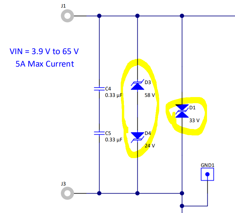
Q1 : We would like to know the purpose for TVS(both uni direction and bi-direction). 

Q2 : And also, if their application is 9V~36V fixed 440W, which means 9V/49A and 36V/12.2A, how can they choose MOSFET for Rdson requirement((20 mV / ILoad(Nominal)) ≤ RDS(ON) ≤ ( 50 mV / ILoad(Nominal)))?

Q3 : For start-up after gate driver is enabled, LM74700 would trying to regulate Vanode - Vcathode to 20mV and fully turn on when Vgate - Vcathode = 12V. Are we right?

Thanks a lot!

Best regards,

Ann Lien

  • Hi Ann Lien,

    D1 is used for transient protection during ISO 7637 pulse 1 test (-150V) on a 12V battery. (D3 and D4 are not needed)

    D1 will not work for 24V battery protection (ISO pulse 600V 50ohm), need to remove D1 and use D3 and D4 instead.

    TVS selection is covered in detail in datasheet application section, if you have more question on this, let us know.

    MOSFET selection is decided at nominal 12V, at 12V, current is 36.67A. MOSFET Rds ON is chosen with nominal current 12.2A and maximum current 49A.

    20mV/12.2A = 1.64mohm (at Vgs 4.5V or 6V) MOSFET can be chosen. But power dissipation at  49A is 3.9W and this needs to be managed thermally.

    Yes during startup, gate driver gets enabled after charge pump is ON. Then gate driver tires to regulate anode-cathode to 20mV and fully turn on when anode to cathode is >50mV.

    Regards,

    Kari.

  • Hello Karikalan,

    Thanks for your input here :)

    We still have one question need your help. May I know why we need to choose 58V and -24V for D3 and D4? Thanks a lot!

    Best regards,

    Ann Lien

  • Hello Ann Lien,

    The breakdown voltage of the TVS+ should be higher than 48-V jump start voltage, less than the absolute maximum ratings of anode and enable pin of LM74700-Q1 (65V) and should withstand 65-V suppressed load dump. The breakdown voltage of TVS- should be lower than maximum reverse battery voltage -32-V, so that the TVS- is not damaged due to long time exposure to reverse connected battery. During ISO 7637-2 pulse 1, the input voltage goes up to –600 V with a generator impedance of 50 Ω. This translates to 12A flowing through the TVS-. The clamping voltage of the TVS- cannot be same as that of 12V battery protection circuit. Because during the ISO 7637-2 pulse, the Anode to Cathode voltage seen is equal to (- TVS Clamping voltage + Output capacitor voltage). For 24V battery application, the maximum battery voltage is 32-V, then the clamping voltage of the TVS- should not exceed, 75 V – 32 V = 43V. Single bi-directional TVS cannot be used for 24V battery protection because breakdown voltage for TVS+ ≥ 65V, maximum clamping voltage is ≤ 43V and the clamping voltage cannot be less than the breakdown voltage. Two un-directional TVS connected back-back needs to be used at the input. For positive side TVS+, SMBJ58A with the breakdown voltage of 64.4V (minimum), 67.8 (typical) is recommended. For the negative side TVS-, SMBJ26A with breakdown voltage close to 32V (to withstand maximum reverse battery voltage -32V) and maximum clamping voltage of 42.1V is recommended. For 24V battery protection, a 75V rated MOSFET recommended to be used along with SMBJ26A and SMBJ58A connected back-back at the input.

    Regards,
    Kari.