This thread has been locked.

If you have a related question, please click the "Ask a related question" button in the top right corner. The newly created question will be automatically linked to this question.

TPS54824: TPS54824RNV Switching Frequency noise

Part Number: TPS54824
Other Parts Discussed in Thread: TPS54424

Hi Team,


My customer are using the TPS54824RNV DC-DC Switching power supply on their new Power Board which includes few DC-DC power supplies (Switching P.S and LDOs) .


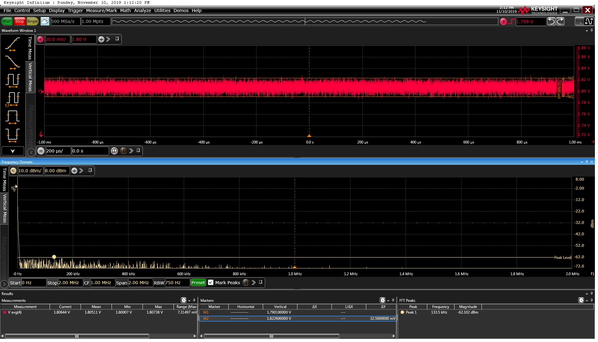
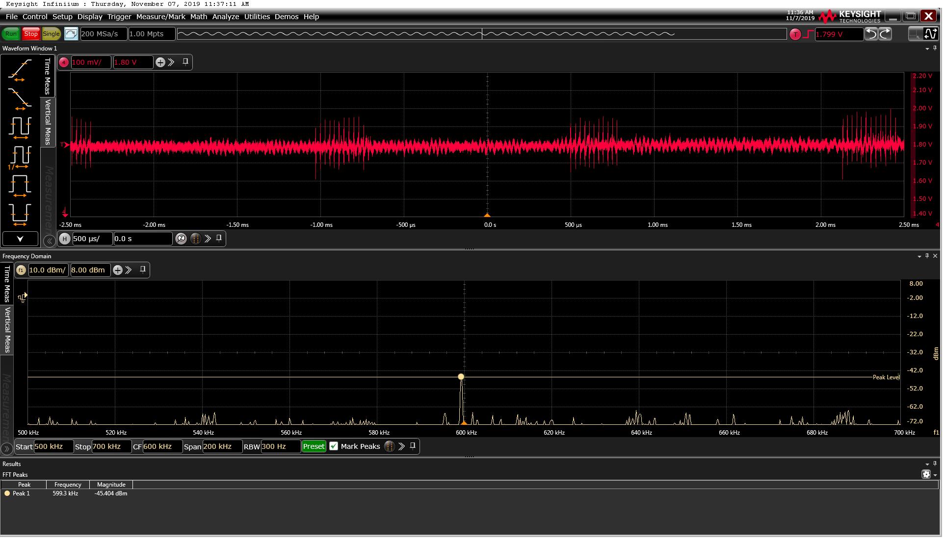
The problem (in one of the Power supplies) that there is noise with DC-DC Switching Frequency (600 KHz) on the Load card which is sensitive to noise.


When they drive the 1.8V to the load using LDO instead od the Switching Power Supply everything is ok.


Please review the below schematic picture and see if everything is ok or suggest them what can be done in order to eliminate/reduce the noise.


Note: The current consumption of the Load is very small and is about 0.5 Amp

Thanks,

Shlomi

TPS54824.docx

  • Hi Shlomi,

        Can you please send us scopeshots of the output ripple voltage  and give us a value of the peak-to-peak ripple that you are measuring?  It would be good to have a good mix of ceramic output capacitors such as 1x100uF, 1x47uF, 10uF, 1x1uF. This will help minimize noise because of capacitor resonances as well?

    Also, this is an 8A converter. Any specific reason that you are using this for a 0.5A application?

    Regards,

    Gerold

  • Hi Shlomi,

    First I want to check and verify that it is noise at the fsw they are concerned about and would like to reduce. It's not higher frequency switching noise closer to 100 MHz, correct?

    Also one more question to add onto Gerold's. Do they have a target ripple voltage this power supply should try to meet?

    To reduce noise at the switching frequency of the converter, increasing the inductance should help. 1.2 µH is relatively low for an application like this. The peak to peak ripple current is ~2A and this is a 0.5A application. With the TPS54824, the could try increasing it all the way to 2.7 µH. If they are ok with changing to a lower current converter, they could try the pin to pin TPS54424 and increase the inductance by 2x higher to 5.6 µH. An even lower current converter will allow a larger inductance but would require a redesign of the PCB.

    If increasing the inductance isn't enough, to get even more filtering, the next thing that would be good to try is adding a ferrite bead to create a 2nd stage filter. I would suggest adding this between the two 47 µF ceramic capacitors if possible.

    Best Regards,
    Anthony

  • Hi Anthony & Gerold,

    Please see below my customer feedback:


    We can’t do ‘drastic’ changes in the Board/design and we want to be able to reduce the noise with minimum changes.


    We calculated again our load current and the calculation of the results is that our load current is very small and is about  50mAmp


    We have few questions:


    1. Does this very small current load  means that using the TPS54824 as power supply is problematic

    If the answer is yes then please explain why the power supply is not good solution for very small loads and what are the limitation

    Do you think that because of this small current load do we have to find other solution in order to fix this noise issue  (that will always exist because of the small load).


    1. Does adding fixed resistor load can Help to reduce the noise

    If the answer is yes then what is the recommended  value of this resistor


    1. Does Increasing the switching frequency can help to reduce the noise

    If the answer is yes then what is the recommended  switching frequency


    1. Why we can’t use indictor for the TPS54824 devise that is larger the 2.7uH

    Thanks,

    Shlomi

  • Hi Shlomi,

    Using the TPS54824 for a small current should not be problematic, it's just not very optimized especially when it comes to cost and efficiency. I'm not sure if adding additional load will help. I think it woudl only have an effect if the noise problem is due to switching noise which is typically near 100 MHz. Can you help check on my first question if they have anyway to know if the noise problem is at the fsw or a higher frequency?

    Increasing the fsw may help. Again it depends on if the noise is at the fsw and its harmonics or due to higher frequency switching noise. It also depends on the PCB layout and how much inductance is in line with the output caps.

    The inductance should be limited to 2.7 µH or less because with peak current mode control the inductor current ripple is used as the ramp for the PWM control. To little ripple results in a small ramp amplitude at the PWM comparator and a small ramp can cause increased jitter. These recommendations are inductor selection in the apps section of the datasheet.

    Have they tried increasing the inductance to see if it gives any improvement?

  • Hi Shlomi,

    Has the customer made any progress with this issue?

  • Hi Anthony,


    My customer now running some tests.


    I couldn’t find the 2.7uH maximum inductor (your answer) limitation in the data sheet.


    Can you find it?


    Thanks,

    Shlomi

  • Hi Shlomi,

    The datasheet has a minimum peak to peak ripple current recommendation of 0.8 A in the Output Inductor Selection section. The maximum inductance varies with the application Vin, Vout and fsw.

  • Hi Anthony,


    My customer made some test in the Lab and they got the following results:


    Using the original 1.2uH inductor and switching frequency of 600kHz:


    The ripple is high and with noise

    There is noise on the 600KHz frequency of about 42dbm (see attached Orig_IND_1.2uH_600Khz.jpg picture)


    Using 2.2uH inductor and switching frequency of 600kHz:


    Using 2.2uH inductor the ripple decreased drastically and the noise on the  600KHz reduced to about 52dbm (IND_2.2uH_600KHz.jpg picture)


    Using 2.2uH inductor and switching frequency of 1200kHz:


    The ripple is small and there is no noise on the switching frequency (up to 62dbm (see IND_2.2uH_1200KHz.jpg picture)


    Using 2.2uH inductor and switching frequency of 1500kHz:


    Almost Same results as on 1200KHz frequency (up to 62dbm (see IND_2.2uH_1500KHz.jpg picture)


    Questions:


    1. It looks that increasing the inductor to 2.2uH improves significantly the results.

    For our test we use Coilcraft 2.2uH inductor (see attached) which we found in our stock and has different Footprint (than the original 1.2uH).

    We want to use 2.2uH inductor with same Footprint and we found the attached 7.5A Wurth inductor (we will not reach higher currents) which we intend to order.

    Can you please approve the new Inductor.

    1. It looks that is better to increase the switching frequency above the original 600KHz

    Since there is are significant changes between 1200KHz and 1500KHz then what is your recommended switching frequency 1200KHz,1500KHz or other frequency?


    Thanks,

    Shlomi

    Wurth_Inductor_2.2uH_7.5A.pdf

    Coilcraft_Inductor_2.2uH_8A.pdf

  • Hi Shlomi,

    Glad to see increasing the inductance helps. I don't expect much difference between the two 2.2 µH inductors and both are good. The Coilcraft one may be slightly better because it has higher self resonant frequency (SRF). The SRF is related to the parasitic capacitance of the inductor and the higher the SRF, the lower the parasitic capacitance. However I think the SRF should have more of an effect at higher frequencies, higher than the fsw of the converter.

    With 12V input and 1.8V output, the maximum fsw I would recommend is ~800 kHz. This is limited by the minimum on-time of the TPS54824. If they changed to the lower current pin-to-pin TPS54424, they could increase the fsw to ~900 kHz and increase the inductance to 3.3 µH.

    I'm also very surprised to see that increasing the fsw had such a significant effect on the noise at the fsw. I was expecting to still see a spike at the fsw of the converter. Where are they measuring the output voltage? On the power board near the converter or on the load board? If it is on the load board, the connection between the boards could be helping to filter the noise.

  • Hi Shlomi,

    Were they able to resolve this?

  • Hi Shlomi,

    I'm going to mark this as resolved but you can reply again here to re-open this.