This thread has been locked.

If you have a related question, please click the "Ask a related question" button in the top right corner. The newly created question will be automatically linked to this question.

TPS22810: Charging supercapacitor with constant current sink, comparator and load switch

Part Number: TPS22810
Other Parts Discussed in Thread: TLC393

Hi,

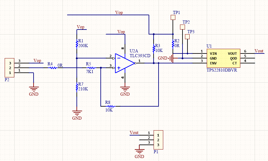
I'm using TPS22810 and TLC393 with a constant current source as the main parts of a supercapacitor charge circuit. The goal is to charge with low current, discharge through TPS22810 when TLC393 trigger his ENABLE pin, and charge again while ENABLE is disabled because Vcap is below the target.

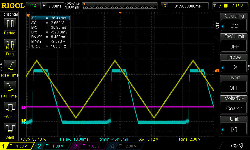
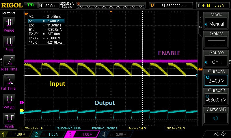
I have two problems: comparator seems to work well with very slow input (power supply controlled by hand...) or with some ramp waveform, but not always, and the other problem is Voltage drop on load switch (and overheat) when output current is higher than available (My supply is limited to 100mA, and I try to get 200mA with a load). The following snapshot was taken in this situation:

This is the schematic:

  • Hi Daniel,

    I cannot comment on the TLC393 device behavior but for TPS22810, it looks like by forcing the current to be larger than its limited value from the supply, the input starts to droop. I do not think your issue is overheating.

    The minimum recommended voltage for correct TPS22810 operation is 2.7V. It looks like the voltage is dropping below that which can cause the device to be insufficiently powered which turns off the device. The input voltage then recovers and the device is sufficiently powered again and the cycle repeats. 

    Does this behavior occur only when you are trying to draw more than 100mA from your supply?

  • Hi Shreyas,

    it looks like by forcing the current to be larger than its limited value from the supply, the input starts to droop. I do not think your issue is overheating.

    I think current across the TPS22810 never is higher than rated

    The minimum recommended voltage for correct TPS22810 operation is 2.7V. It looks like the voltage is dropping below that which can cause the device to be insufficiently powered which turns off the device. The input voltage then recovers and the device is sufficiently powered again and the cycle repeats. 

    I expect Vin to be lower than 2.7V sometimes, but if device is off during this period is ok for me. The problem would be if the behaviour is weird like the previous waveform.

    Does this behavior occur only when you are trying to draw more than 100mA from your supply?

    Yes, every time I put a load draining more current than available: 100mA power supply and 200mA load, 40mA power supply and 80mA load...

    The load gets is current, but with lower voltage, so the V difference drops into TPS22810, and I dont know why behaves like that.

    Another thing which may be useful: Comparator output is 1 all time, seems like not working, but oscillations in his input (TPS22810Vin) goes from high to low threshold (Places where comparator sets an 1 and when reset to 0). 

  • With 1kHz square signal at enable, TPS22810 output is allways enabled.

    With 10Hz square signal at enable, TPS22810 output is high when high part of the square, and ramp low a little when EN is low.

    Ramp almost disappears increasing the load (some mA), but increases again with frequency. I have CT and QOD floating, any other adjust can be better? 

    Maybe TPS22810 is not the best suited for this quick switching job?

    Attending to the TPS22810 datasheet page 7 (Switching Characteristics), switching frequency varies from 189uS (5,29kHz) and 524uS (1,9kHz).

  • Hi Daniel,

    I do not think there is any voltage that is being dropped across the device when you have more than 100mA of current. From your scope shot it looks like your input is dropping. This makes sense if your power supply is power limited. You said that it was rated for 100mA only. Thus the voltage is dropping to unsustainable levels for the device to function correctly. I highly doubt the current flow or overheating is the issue here.

    Secondly are you referring to the t_on time as the switching frequency in the case of a PWM? Timing is incredibly voltage and load dependent and is also dependent on what capacitor is on the CT pin. You have to take into account the delay time, rise time, turn off and fall time for an entire PWM cycle. Please refer to Figure 17 on the datasheet to see hoe TI defines these specs. It makes sense that you are seeing an incorrect response if you are PWM'ing the enable pin faster than the device can go through its entire cycle.

  • After adding some capacitor to improve the stability I've got this waveforms:

    100Hz enable ramp waveform (yellow), output (cyan)

    500Hz enable ramp waveform (yellow), output (cyan)

    Seems like TPS22810 is not able to do this high speed switching job successfully.

    What parts you recommend to replace this? I've thinking in all passive high side switching circuit or use some high side driver

  • Hi Daniel,

    Why did you pick TPS22810 initially? Was there any specific feature of the TPS22810 that is necessary for your circuit?

    What voltage and current ranges do you expect for the application in all use cases? 

    While TI might have some switches that respond fast enough, they may not have the integrated features that TPS22810 do.

  • Hi, 

    I'm using TPS22810 in other parts of the circuit so I tried to see it it can be used also in this other use case.

    The voltage and current thar this switch needs to handle are 9V and 100mA, some peak of 400mA maybe...

    What parts do you recommend? 

  • Hi Danielle,

    At that voltage level, the only load switch that could work is the TPS22810 but it does not have the switching capability for your application. 

    Unless you PWM slower, this device will not work correctly for this application.