This thread has been locked.

If you have a related question, please click the "Ask a related question" button in the top right corner. The newly created question will be automatically linked to this question.

WEBENCH® Tools/LM25085: Alternate method for calculating Minimum Ripple component values

Part Number: LM25085

Tool/software: WEBENCH® Design Tools

I have designed a regulator which provides 12V @ 3A with an input of 12.5V to 24V. When I calculate the values for the minimum ripple configuration using the LM25085 data sheet description (8.2.2.6 R3, C1, C2) or the LM(2)5085 Quick Start spreadsheet I get R3=12.7k, C1=3300pf  and C2=0.1uF . This results in terrible Line regulation, with the output varying from 11.7V to 12.7V as the input voltage is changed from 13V to 24V. 

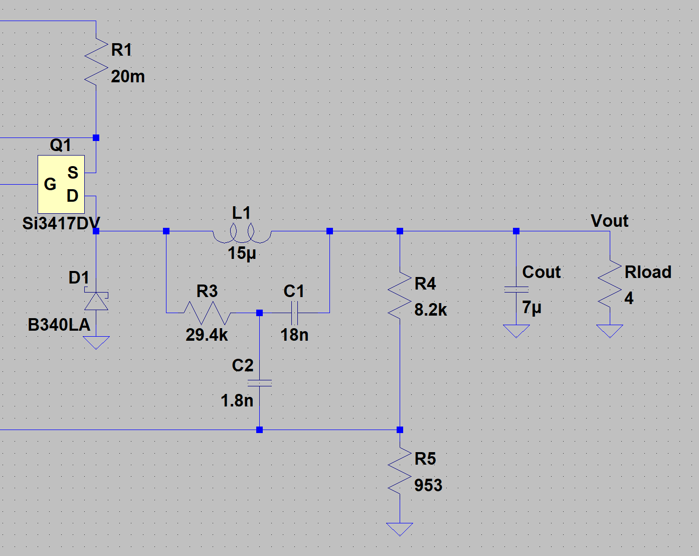
When I used WEBENCH it configured those components differently, with R3=29.4k, C1 = 18nF, and C2 = 1.8nF. These values gave much better results with the simulated output varying from 11.96V to 12.14V as the input was varied from 13V to 24V. Is there any application note, spreadsheet or other guideline for selecting these components in the way that WEBENCH chose them, rather than the approach described in the data sheet? It seems that having a small value for C2, rather than an arbitrary large value like 0.1uF, is very important, but I'd like to know how to optimize the values to match my circuit.

  • Hi Michael:

    the major reason that R3=29.4k, C1 = 18nF, and C2 = 1.8nF is better than R3=12.7k, C1=3300pf  and C2=0.1uF , is becasuse the AC voltage couple on the C1 redcued. 

    Vc1_ac~=Vsw*ton/R3*C1

    the output votlage is equal to K*(FB+0.5*Vc1_ac), K is divdie ratio. so when C1 is large, the ac voltage is small and it doesn't change a lot by Vin. that's why you can see the line regulation is good.

    but we will suggest that the injection into Vfb better higher than 25mV, so higher injection votlage will make the output more stable but line regulation poor.

    Thanks

    Daniel Li

  • Hi Daniel,

    Thanks for your reply. The part I want to understand better is why C2 is much smaller than C1 in the WEBENCH version. I was thinking maybe this is some kind of phase compensation, or reducing noise coupling into the feedback node. Any additional information on how WEBENCH came up with its component choice would be greatly appreciated.

  • Hi Michael:

    pls check whether below AN notes is help to you

    http://www.ti.com/lit/an/snva874/snva874.pdf

    Thanks

    Daniel Li

  • Hi Daniel:

    Yes, that App Note gives a good explanation for how the components relate, and the equations at the end give results much closer to the values I got from WEBENCH, and specifically they use a small value coupling cap (like WEBENCH) which seems to give better results. 

    Incidently, I wasn't able to get good results using the unencrypted Spice model until I went in and modified RDUMMY to be 2.3 ohms instead of 50 ohms. This is the PFET gate driver resistance, and the model works much better once this is changed to match the data sheet.

  • Hi Michael:

    Glad to know it is helpful. 

    I would like to close the question If you don't have further question about C2 value. but if you have any more question, you can reopen this and we will help  answer the question. 

    Thanks

    Daniel Li