This thread has been locked.

If you have a related question, please click the "Ask a related question" button in the top right corner. The newly created question will be automatically linked to this question.

TPS53353: TPS53353 PGOOD pin cannot be high-impedance when output is good

Part Number: TPS53353

Hi team,

Our customer meet some problem with TPS53353 PGOOD pin. Please refer to the detail information below.

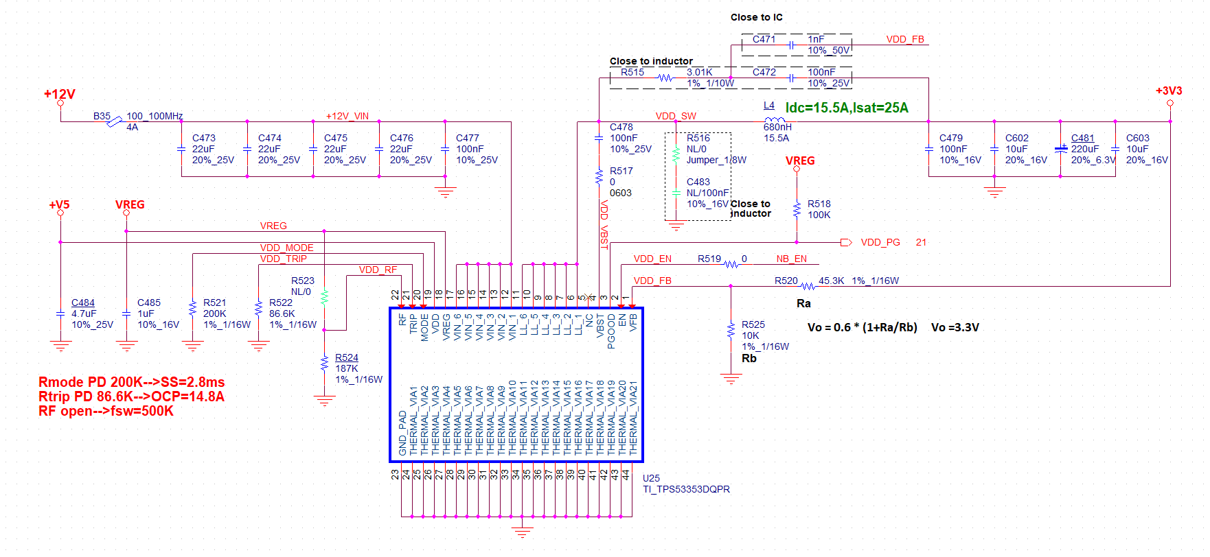
1. Our customer do the test with 4 pcs tps53353, only 1 pcs works good, other 3 pcs all meet the issue

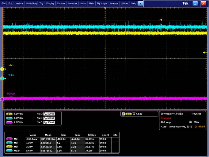
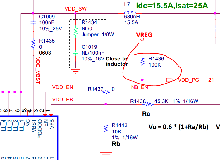
2. PGOOD pin is pull up to VREG through 100kohm resistor, VREG is 5V when the output of TPS53353 reaches 3.3V, but PGOOD pin is not high when Vout=3.3V

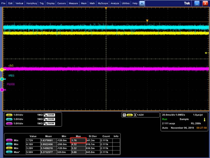
2. We change the 100kohm pull up resistor to 100ohm, PGOOD pin is 1.6V now.

3. We remove the pull up resistor R1436, and also the 0ohm R1453 connected to LED string, to make PGOOD pin floating, and we test the impedance to ground of PGOOD pin, it's about 800k when the device is not power on, and it decrease to 40ohm after power on.

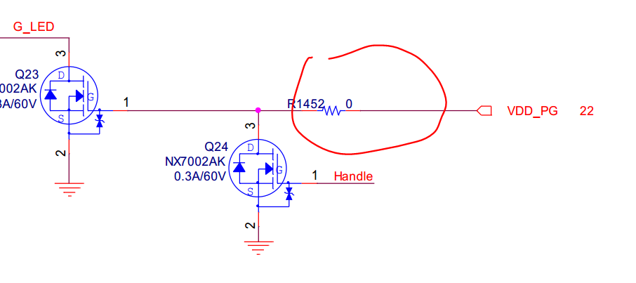
We also do the test with the good one, the impedance is about 800k after power on, so the PGOOD pin can be pulled high.

Could you please give some comments on what may be the issue cause?

Thanks.

Best Regards,

Livia Liu

  • Hi Livia,

        The voltage being 1.6V when using 100 ohm is because of the voltage divider formed by the on-resistance of the pull down FET in the power good pin. So, even when it shows 1.6V, the PGOOD is still getting pulled down.

    Can you try swapping the device on the working and non-working board? This can confirm if the issue is following the device or the board.

    If you can share the pdf of the regulator schematic, it will gives us a better picture if some thing is wrong with the design?

    Regards,

    Gerold

  • Hi Gerold,

    Thanks for the quick reply.

    We've done the test by swapping the device on the working and non-working board, it ends up that the  the issue is following the board.

    Please refer to the schematic as below. Could you please give some comments on what may cause the issue?

    Thanks.

    Best Regards,

    Livia

  • Livia,

    Check the ripple voltage at the RC across the inductor (junction of R515 and C472) and the ripple at the FB pin of the TPS53353 ( junction R520 and R525)

    The PGOOD driver is controlled by a comparator on the FB pin that is looking for the FB pin voltage to be within a +/- 10% window of the 600mV reference voltage.  If there is a lot of AC ripple on the FB pin and it is tripping the PGOOD comparator, the PGOOD pull-down will remain even if the average output voltage is within regulation.

    The attached schematic should have 16mV of ripple at the R-C across the inductor if R515 and C472 are correct.

    The inductor current ripple should be about 7A pk-pk.  With only 2x 10uF for ceramic capacitance, the output ripple will be primarily defined by the ESR of the 220uF electrolytic capacitor.   That could produce a lot of ripple depending on that capacitor's ESR.

    If the ripple on the output is more than 80mV (12mOhms ESR) the design does not need the R-C across the inductor because the electrolytic capacitor has enough ESR to produce enough AC ripple.

    I would also recommend checking the RMS ripple current rating of that electrolytic capacitor as the 7A pk-pk inductor current ripple may be exceeding its RMS ripple current rating.