This thread has been locked.

If you have a related question, please click the "Ask a related question" button in the top right corner. The newly created question will be automatically linked to this question.

BQ25505: Current leakage

Part Number: BQ25505

We are implementing the BQ25505 and it seems to be working pretty well except for the fact it seems to be drawing more current than what the circuit actually calls for.

We can power the circuit without the BQ25505 we will draw only around 10uA.  But with the BQ25505 inline it seems to consume about 2mA for whatever reason.

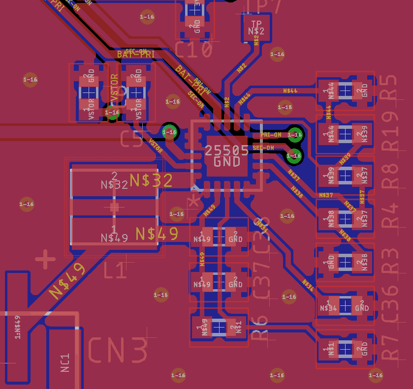
Hope you can give me some ideas here.  Attached is the schematic and pcb.

Thanks for your help

  • Henrique,

    Is the circuit drawing 2 mA with the rechargeable battery is connected? The unexpected draw may be due to the battery charging. To confirm this theory, could please provide the input voltage, input current, battery voltage, battery current, system voltage, and system current under the condition of the battery attached and detached.

    Thanks,

    Ricardo

  • I should have stated that I don’t have the rechargeable battery in circuit yet.  

    When I  did have the rechargeable installed,  I saw it charging fine.    I’m doing this test without it for now.

    I’m in the process of looking for current leakages.

  • Henrique,

    Is the input voltage always less than the VSTOR voltage? If the device is not operating in boost mode, there is an internal FET that pulls VIN_DC to GND. TO investigate this theory, could you provide a scope capture of the SW pin, the voltage at VIN_DC, and describe to me how you are power the device in your experiments (is from a low impedance bench power supply or a high impedance source such a solar panel)?

    Thanks,

    Ricardo

  • Hello,


    I have not heard back from you in a while. Please let us know if you have any further questions, otherwise I will be closing this thread.


    Thanks,

    Ricardo

  • Hi sorry, I was on vacation

    not familiar with the SW pin

    I'm testing it right now with a lab power supply.

    • vbat_Pri is usually set to 3.6V
    • and Vin_dc is generally set to 5V set at 300mA maximum
    • a 3.7V / 850mAh lipo sits at vbat_sec

    we programmed our chip to have:

    • vbatt_ov=4.0V
    • vbatt_ok=3.1v
    • vbatt_hyst=4v

    the battery is charging right now.  Vbatt_ok test point is not active.

    the following is a screen capture of the lboost pin

  • Henrique,

    Your input voltage (VIN_DC) is greater than your VBAT_OV threshold. This charger is designed to act as a boost charger. In a boost charger, the input voltage is less than the battery voltage. In BQ25505 whenever this occurs the first NFET in the functional block diagrams turns on and current flows as I have shown to ground. This seems like the most likely source of your leakage current. To prevent this, I suggest lowering your input voltage or clamping it appropriately for your design.

    Thanks,

    Ricardo