This thread has been locked.

If you have a related question, please click the "Ask a related question" button in the top right corner. The newly created question will be automatically linked to this question.

LM3414HV: increase input capacitor for PWM

Part Number: LM3414HV
Other Parts Discussed in Thread: LM3414

Hello 

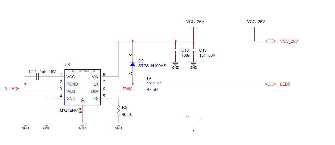
i am using the following configuration for my light system. 

The driver is connected to 2 serial Cree xhp35 using 26V with 1A .

I want to increase the number of LED in my system but the battery of my robot cannot support enough peak current for driving all my LED (i have a around 20 Led driver in my system)

i am using the LEDs in PWM for a short 5ms exposure time at rate of 4 HZ. 

I Want to use a big capacitor but i am not sure where to locate it in the schematic.  in addition when i am adding the capacitor how will i know the charging time of the capacitor  ? i i dont know the Resistance of the driver  (t = RC) 

Thanks 

  • Hello Aviad,

    From the Cree datasheet it appears the Vf of the LED is around 12.3V at 85 Celsius.  It will be higher when the LEDs are not as hot.  Two in series would be 24.6V at 85 Celsius.  If Vin is 26V you may be running into input voltage limitation or not enough voltage headroom.  Since the LED voltage is near the input voltage I will just use 1A as the source current.  Using I = C*(dv/dt) and setting dv at 1V (this is how much the voltage will droop during the 5 ms pulse), the capacitor value for hold-up would be 5000 uF.  This assumes the battery is not supplying current during the 5 ms pulse.  If the voltage droop, dv, is set to 0.5V the capacitor value will double, or 10,000 uF.

    Best Regards,

  • Hi Irwin

    Thanks for the reply. it was very helpful.   

    i have several more questions:

    1.  I just want to validate that the capacitor should be place in C_in in the Manuel ?   

    2. i am afraid that the system consume too much current for charging the capacitor at t=0 after i finished triggering one LED cycle ? The Vin of the Driver is connected directly to the battery with a fuse so the resistance of  the system is very low =~ 0, Therefor the maximum current will be too high  i = dv/R.

    3. if i want both battery and capacitor to supply the current to the LED , is it possible? Most of the current will be from the capacitor  ?

    4. Where is the dv (voltage difference) lost in the system , is it on resistance in the LED driver? 

     5 . I did saw that when i am increasing the input voltage 28V i have more light and the input current is 100mA higher ( in both cases it is set to 1A) , is it be related that the my LED Vf is higher then 12.3V because my PCB is not warming up at all (around 40C) ?    

    Thanks Again 

    Aviad  

  • Hello Aviad,

    1)  This bulk capacitor should be in parallel with C18 and C19 of your schematic if that is the question you are asking.

    2)  You can add a power resistor in series with the capacitor to charge it, the LM3414 should remain tied directly to the capacitor after the charging resistor.  Note that the resistor needs to be sized to charge the capacitor from zero volts for initial charge (this is the pulse rating).  You can also design a current source to charge the capacitor, SOA needs to be taken into account if this is done linearly with a MOSFET circuit.

    3)  Yes, this is just the math to size the capacitor.  If you can measure how much current the battery supplies you can subtract that energy from the capacitor calculation.

    4)  Which dv (voltage difference), there are many.  The LEDs have a series impedance, the source has a series impedance, not sure what you are asking?

    5)  Most likely.  You can just measure it with an oscilloscope when it is running.  The two voltages are close enough this may be difficult to do.

    Best Regards,

  • Hi 

    Thanks again for the reply.

    Regarding :

    4)  Which dv (voltage difference), there are many.  The LEDs have a series impedance, the source has a series impedance, not sure what you are asking?

    i am asking because i want to know how much power i am losing in my system. i am running a Autonomous robot underwater for a long time and i need to measure the power i am losing in my system. 

    Thanks again for all the help, i got all the answer i needed ! 

    Aviad