This thread has been locked.

If you have a related question, please click the "Ask a related question" button in the top right corner. The newly created question will be automatically linked to this question.

LMZ31710: LMZ31710

Part Number: LMZ31710
Other Parts Discussed in Thread: TPS54A24, TPSM84824, TPSM84424

Hi,

I'm designing a project with requirements for different types of switchers.

I have an input voltage of 10V and I need to deliver the following voltages to me circuit (derived from the 10V):

  • 8V --> 1.5A
  • -5.25V --> 0.95A
  • 5.25V --> 19A (can be divided up to 4 ICs)
  • 3.5 --> 8.3A (can be divided up to 2 ICs)
  • 2.2 --> 10.46A (can be divided up to 3 ICs)
  • 6.25V --> 6.15A (can be divided up to 2 ICs)
  • 5.7V --> 2A
  • 4.3V --> 0.25A

The main problem I have is that I need to synchronize all these components to 3 possible options:

  1. Fixed 1.25MHz
  2. Fixed 2.5MHz
  3. Variable 200-300KHz --> meaning I will change the frequency every few microseconds between 200-300KHz with fixed step (could be lower bandwidth, but inside these limits).

Can you help me find converters which can cover the above requirements?

I looked at LMZ31710 but the sync can reach up to 1.2MHz, and I think I can't use option 3 for synchronization because it needs fixed frequency.

Thank you,

  • Hi Efi,

    You mentioned LMZ31710 -- are you looking for power modules (integrated inductor) specifically? 

    For many of these rails (8V, 6.25V, and 5.7V outputs), please take a look at the TPSM84824 (8A) and TPSM84424 (4A) modules. You could synch those devices to 1.25MHz. For the 3.5V 8.3A, the discrete TPS54A24 can be used and synchronized to 1.25MHz as well.

    Do all rails have to use the same synch option or will all 3 be available to individual rails? In other words, can some rails be synchronized to 1.25MHz, some to 2.5MHz, and some to 200-300kHz, or all rails have to use the same one option?

    Some of these rails are at relatively high current. What is the effective ambient temperature in your system?

    Kris

  • Hi Kris,

    Thank you for your answer,

    Kris F said:

    Do all rails have to use the same syncי option or will all 3 be available to individual rails? In other words, can some rails be synchronized to 1.25MHz, some to 2.5MHz, and some to 200-300kHz, or all rails have to use the same one option? each rail can work with different synchronization method.

    Some of these rails are at relatively high current. What is the effective ambient temperature in your system? -40ºC ÷ 60ºC

    I have more supplies I need to design power to, but I still need to finalize the requirements. I will post my requirements soon. the sync 

    Thank you,

    Efi

  • Thanks for the info, Efi.

    Would you be able to use an LDO for the 4.3V 250mA rail coming off of the 5.7V output?

    For the -5.25V rail, you may need an inverting buck boost, in which case you'll need to level shift the synch and other signals which can add some complexity to the design. Since this -5.25V rail is relatively low current, would you be open to have this rail unsynchronized?

  • Kris F said:

    Would you be able to use an LDO for the 4.3V 250mA rail coming off of the 5.7V output?

    Yes

    For the -5.25V rail, you may need an inverting buck boost, in which case you'll need to level shift the synch and other signals which can add some complexity to the design. Since this -5.25V rail is relatively low current, would you be open to have this rail unsynchronized?

    I'm trying to get the -5.25V from system supply so we can let it go for now.

    I have the rest of voltages I need with the same restriction about the synchronization:

    derived from 5V:

    3.6V --> 2.3A

    next voltages can be derived from 5V or 3.3V (preferred 5V, dependent on efficiency):

    2.1V --> 3.4A

    1.5V --> 6.6A

    0.95V --> 30.5A FPGA core

    1.03V --> 5.6A

    1.2V --> 0.32A

    1.8V --> 3.7A

    0.9V -> 1.6A

    3.6V --> 3.3V    2.3A regulator

    2.1V --> 1.8V 3.4A regulators (can be divided up to 3 ICs)

    1.5V --> 1.2V 6.6A regulator (can be divided up to 4 ICs)

    3.3V --> 3V 0.15A regulator

    3.3V --> 2.5V 0.1A regulator

    Can you please help me apply power supplies to the above rails?

    Thank you again,

    I really appreciate it,

  • Hi Efi,

    It may be more efficient to discuss through email. Can you please email me at kristoffer.flores _at_ ti.com?

    I am putting some of my questions and comments here and we can continue the discussion in email.

    There are many rails here, and I want to make sure I understand which outputs you need to be derived from which intermediate/bus voltages etc. For example, is the 5V you mentioned above a separate source from the 10V input from your first post, or the 5V is derived from the 10V (and is it the same as the 5.25V you first mentioned, and the 19A is the total input referred current you expect)?

    I am compiling a block diagram based on my understanding and we can work together on filling that up with power recommendations for each rail. 

    What FPGA are you using? Perhaps we already have a reference design showing a power solution for it.

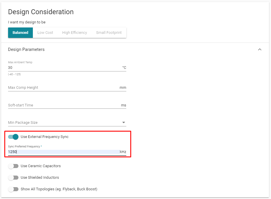
    In addition to looking for a reference design for your FPGA, we can use WEBENCH Power Designer as a starting point to see the potential solutions for each input to output voltage/current requirement. In the tool, you can specify the requirement for an external synchronization frequency and the solutions presented will be devices that can support that synchronization frequency based on the tool's efficiency, thermal, and other (timing, current limit) calculations.

  • Efi, do you still need assistance with your power tree?