This thread has been locked.

If you have a related question, please click the "Ask a related question" button in the top right corner. The newly created question will be automatically linked to this question.

BQ76940: AFE goes into SHIP mode during Radiated Immunity testing

Part Number: BQ76940

Greetings,

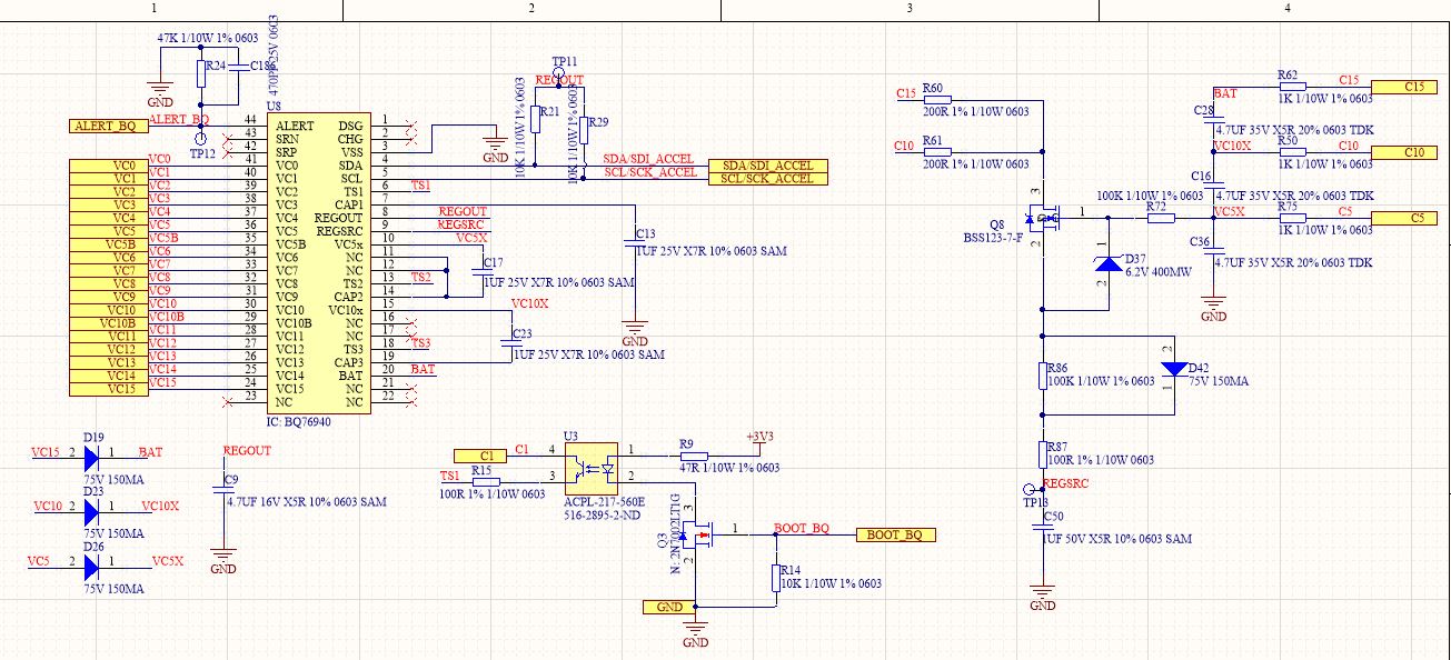
We are having a BMS solution that uses the above mentioned component. 15S BMS with support for 3 temperature sensors. The schematic for this section is as per attached image:

While performing Radiated Immunity testing as per IEC 61000-4-3 @ 15V/m (Which is very low intensity radiation), we have observed failures that have the following consequences:

- Voltages and temperature readings start fluctuating at the start of the test @ 80 MHz

- The AFE goes into SHIP mode at a particular frequency, and no response seen on I2C.

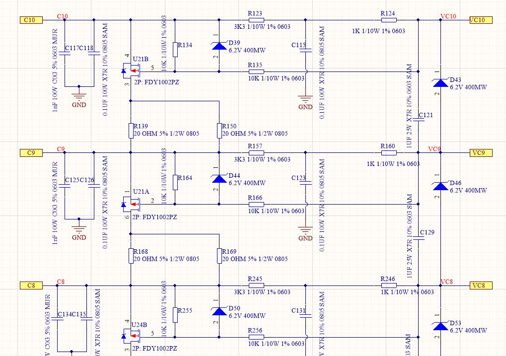
In order to isolate the source of the fault, we tried the immunity test for the entire frequency range with only the voltage harness connected (Voltages were always fluctuating throughout the test) Magnitude of reported fluctuation was +/- 500mV. It is to be noted that the differential filter network as per reference design on the cell sensing lines is not able to manage the common mode noise.

Example of the filter network is as follows:

We then added the thermistor harness which contains 10k NTCs. The voltages and temperatures both were fluctuating and at a particular failure frequency (~300 MHz), the AFE crashed and went into the SHIP mode, which is not acceptable as the test standard. This calls for a BOOT of the AFE.

By placing additional snap on ferrite beads on all the NTC channels, we were able to manage the perturbations enough to not force the AFE into the SHIP mode, which is confirming the source of noise being via the temperature harness.

Placing snap on ferrite beads is an expensive solution for mass production since the annual production volume for this product 200,000 units and needs to be handled at the design level using filtration.

It would be fair to say that the perturbation is near VC5X/VC10X as soon as the NTCs are interfaced.

My questions would be as follows:

- Has any immunity testing been performed with the design recommendation? If yes, what's the level of the electric field and frequency sweep that is managed?

- What can be the root cause for the AFE to go into the SHIP mode under these circumstances?

- Are there any design recommendations (Additional filtration) that is recommended by TI for management of EMC? How would a collaboration of common mode and differential filters be managed with external balancing?

Thanks!

  • Hi Rachit,

    The BQ769x0 component is not tested to IEC 61000-4-3 or other EMC standard.  The application circuit is a basic functional circuit.  Dealing with fields in the system environment may need special circuits beyond the standard application circuit.  Wiring harnesses to cells can be very effective antennas and attenuating the RF fields picked up in the harness may be required.  Consider the PCB also avoiding loops and using planes where needed.  Electronic systems designed for high field strength environments often have filter networks at the connectors where signals enter a board.

    The BQ76940 may go to ship mode if reset.  Reset is defined on the BAT voltage, specifically VC5X to VSS.  Shorting the CAP1 pin can apparently leave the part in ship mode. Disrupting circuits or power supplies by shifts in the reference points of capacitors can cause disruptions, pulling signals below VSS can reset some integrated circuits.  The BQ76940 is known to not start properly when TS2 or TS3 pull downs are referenced below the VC5X or VC10X nodes, noise pulling TS1 below VSS may be causing a reset from your description. 

  • Hi WM5295,

    Thank you for your feedback.Could you explain this point:

    [ quote user="WM5295"]Reset is defined on the BAT voltage, specifically VC5X to VSS. [/quote]

    It seems clear to us that the perturbation on the VC5X/10X lines is causing the AFE to go into the SHIP mode.

    We evaluated to have a Y-cap to GND and a low pass filter on the temperature lines, however it is not possible to use them because of the Rfilter + NTC value will be seen by the ADC while the measurement turns on. Could you suggest strategies of managing filtration on it?

    Also, it would be nice to have your feedback on this strategy on cell filters, where we manage the common and differential mode filtering both. Do you see any potential problems in turning on the external balancing channels? Could you recommend some example circuits that can be used to manage the RF fields?

    Thanks and BR,

    Rachit

  • Hi Rachit,

    While VPORA and VSHUT are the defined reset condition, other pin disruptions can cause the part to reset.

    We don't have a reference design for high EMI enviroments.  It may be best to work with an EMI expert familiar with your system requirements and industry.