This thread has been locked.

If you have a related question, please click the "Ask a related question" button in the top right corner. The newly created question will be automatically linked to this question.

PMP9490: I copied the schematic of the PMP9490 and the integrated one makes a loud noise that rises in frequency when I put a load on the Vout output until it heats up and breaks.

Part Number: PMP9490
Other Parts Discussed in Thread: LM5175, , LM5176

Hi.

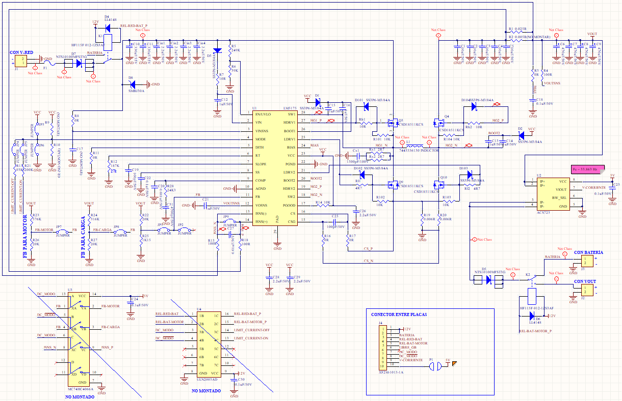
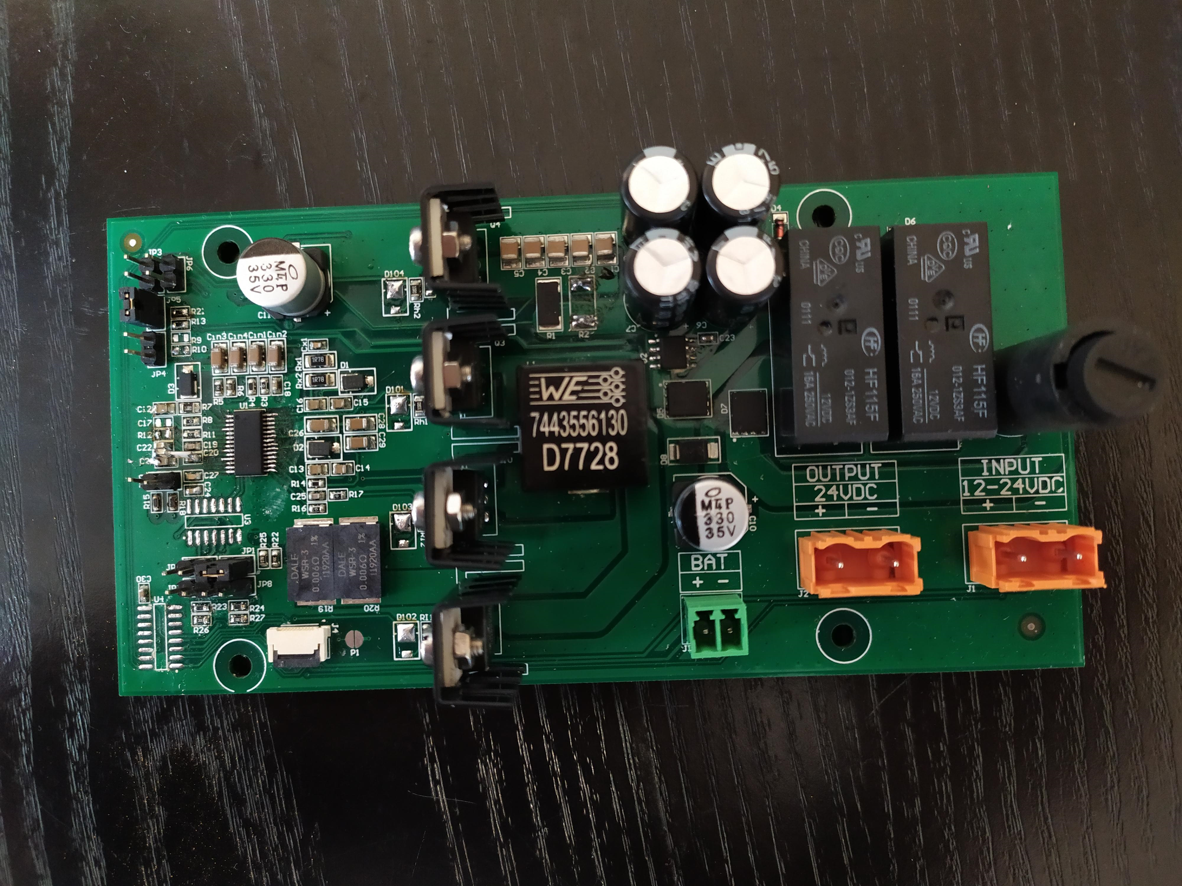
I copied the schematic of the PMP9490 board and made the design of the PCB placing the components as recommended by the data sheet of the LM5175.

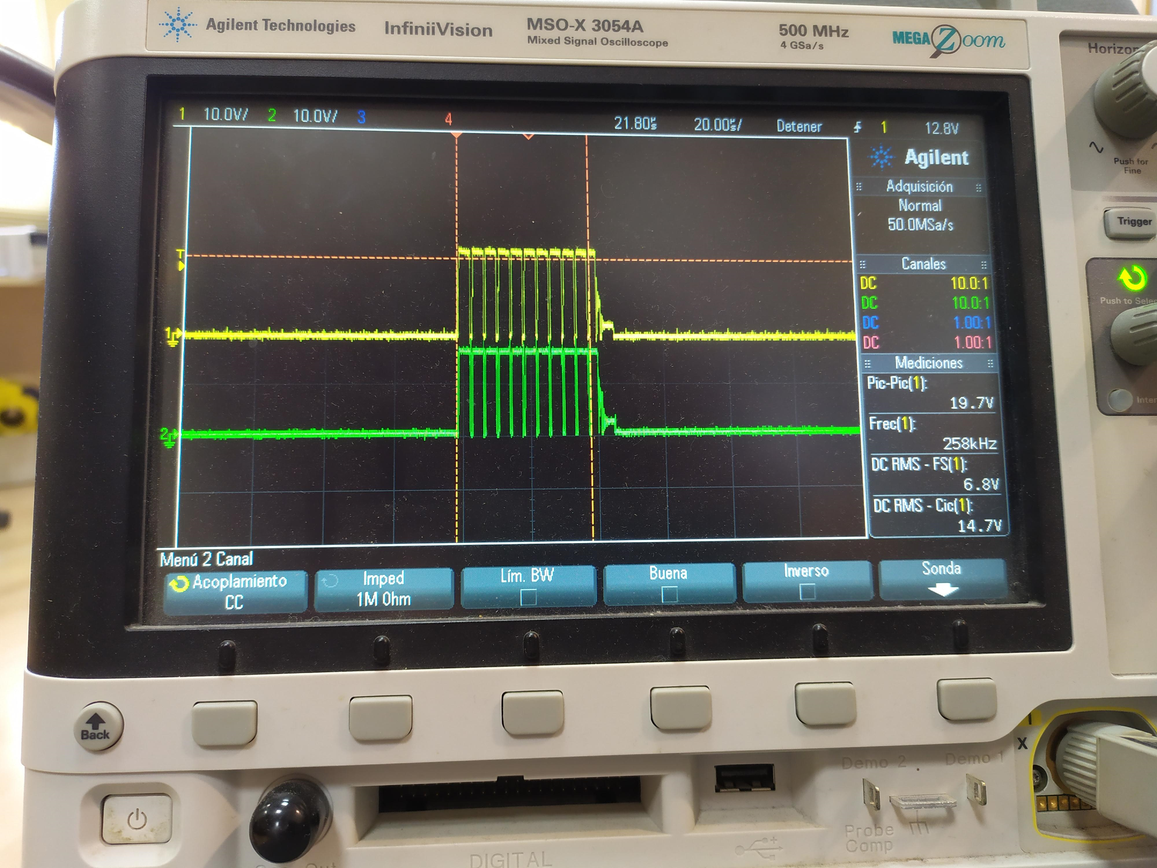
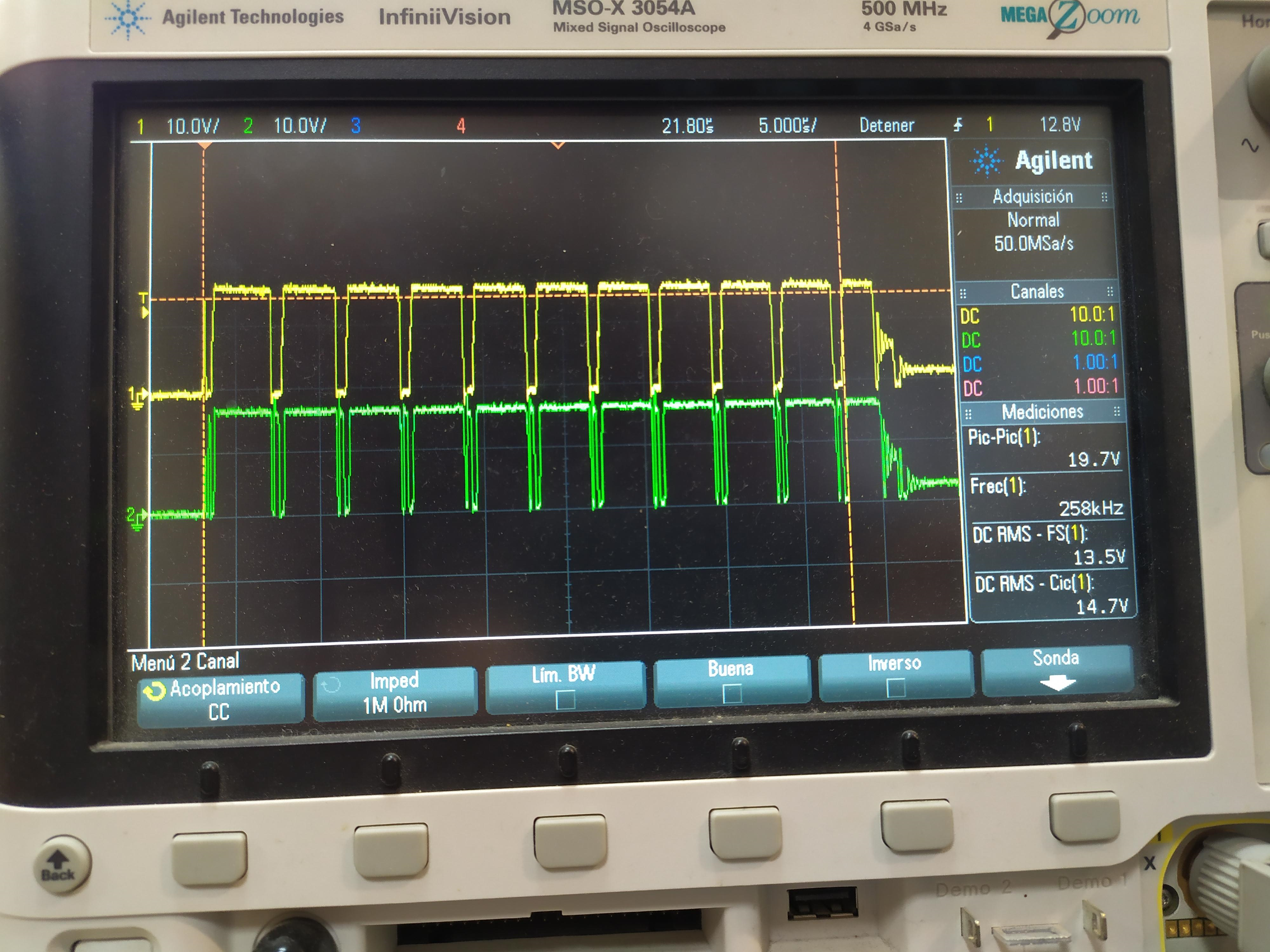
I've only got it to work in Buck mode and the integrated one makes a loud noise that rises in frequency when I put a load on the Vout output until it heats up and breaks.

What can be caused by this buzzing sound in the integrated LM5175 and why can it be heated? Can there be any typical fault in the circuit that causes this result?

Greetings.

  • Hi Ramon,

    First, thank you for your interests in our product LM5175.   It sounds like your circuit is not stable.  Please monitor SW1 and SW2 and show us the the scope picture. 

    If you wish, you can send your schematic for a review.  We found some times mistakes could be introduced during copying our schematic.

    Thanks,

    Youhao

  • Good morning, thanks for answering.

    I enclose the circuit diagram, the measured signal of SW1 (yellow color) and SW2 (green color) and a photo of the PCB.

    Current situation of the circuit for the tests performed:

       1.- I have changed the LM5175 to the LM5176 and changed the RT resistance to 30K. These images that I have attached are with the LM5176.

       2.- I have put the MODE pin to GND with a 200K resistor.

       3.- The U3 and U4 ICs that appear in my schematic have been removed to ensure that they do not cause problems.

       4.- Jumper JP1 inserted.

       5.- Vin = 17V

       6.- Vout = 14.3V

       7.- If I load the IC LM5176 increases the frequency of audible sound noise.

       8.- If I increase Vin> 17V and do not put any load, I will regulate the Vout = 14.7V, if I decrease Vin <17V Vout it will decrease.

    Buck-Boost.pdf


    Greetings, I await your response thank you.


  • Thank you for the info. 

    From your schematic, you used 0 Ohm at R16 and R17.  Can you use 100 Ohm each and change C23 to 1nF, 2.2nF, upto 4.7nF and see if there is any improvement?

    From the layout, I found you did not follow our datasheet layout guideline, nor referring to the EVM layout pattern.  Both buck and boost switching legs use the current sense resistor.  So, the layout should be symmetrical.  Also, you ac current paths form a large loop, introducing inductance, and hence causing noise. Please refer to our EVM example to place and route connections between the MOSFETs, input and out capacitors, current sense resistors.  Also pay attentionto the current sense Kelvin sensing and gate drive traces.  The gate drive and return traces should be closely side by side. 

    Best Regards,

    Youhao

  • Good morning Youhao and thanks for replying.

    Could you pass me the PMP9490 project to import it?  I have seen that all the documentation of gerber and schematics is present, but not having the project would have to do reverse engineering to be able to start from something that works well.

    Greetings I await your response.

  • Hi Ramon,

    We will try to get the native PCB design files for you.  This may take a few days.

    thanks,

    Youhao

  • Hi Youhao,

    Thank you very much I will be waiting.

    A greeting.

  • Hi Ramon,

    Thanks for your patience. I will send you a friend request so the files can be transferred.

    Let's close this thread here.

    Thanks,

    Richard