This thread has been locked.
If you have a related question, please click the "Ask a related question" button in the top right corner. The newly created question will be automatically linked to this question.
Hi Emma,
According to BC1.2 spec, the transition between CDP and SDP needs the discharge state.
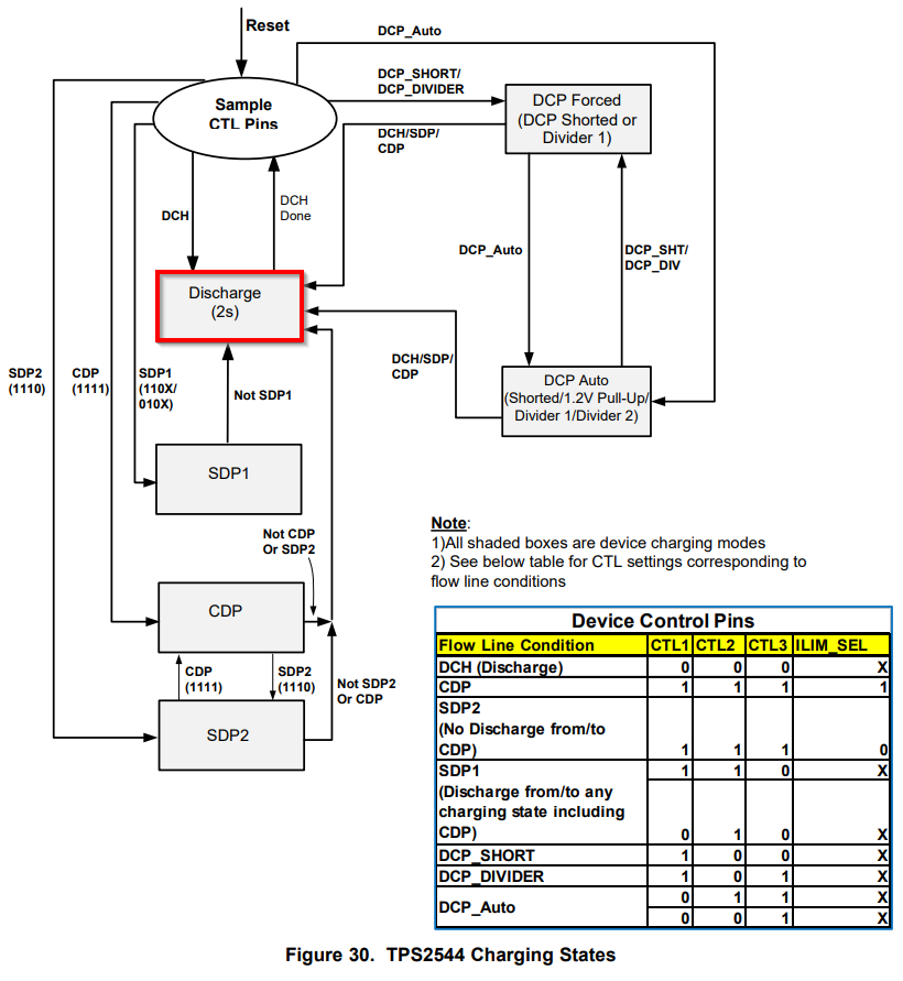
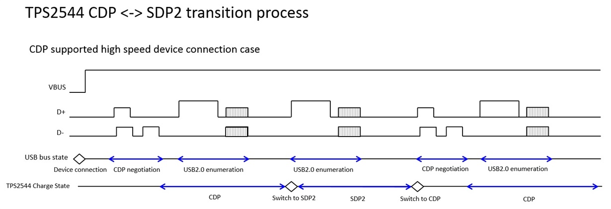
Figure 30 of the datasheet shows that the transition between CDP and SDP2 doesn't go through Discharge.
Does it mean that the discharge state occurs automatically if our EC set CTRL* and ILIM_SEL from CDP to SDP2 (or from SDP2 to CDP)?
Thank you.
Katsuhiro
Hello Katsuhiro,
The discharge state does not occur during the transition between SDP2 and CDP. There is no OUT discharge when switching from SDP2 to CDP or CDP to SDP2. This is done to prevent a dataline disconnect that happens during discharge.
The other modes that go through discharge are captured in the flow chart from page 19 of the datasheet pasted below:
Thanks,
Emma
Hello Emma,
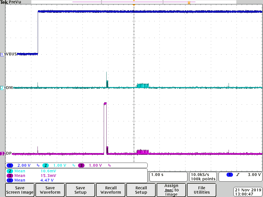
Would you provide me the waveform of D+/D- and VBUS when the transition from CDP to SDP2 (or from SDP2 to CDP) is performed?
I would like to know the procedure of the transition between CDP and SDP2 without discharge.
Thank you.
Katsuhiro
Hello Katsuhiro,
I will get the scope capture back to you in the next few days. If you have a TPS2544EVM, you can also test the transition.
Thank you,
Emma
Hello Katsuhiro,
Test 1
Below is a scope capture of plugging in a flashdrive to the TPS2544 in CDP (1111) and then adding and removing the jumper on ILIM.
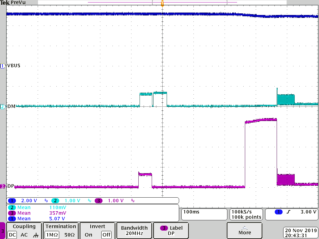
Test 2
Below is another scope capture of plugging in a phone in CDP (1111)
and adding/removing the jumper on ILIM to move to SDP (1110).
The purpose of this feature (switching between CDP and SDP2) is for a host to switch to SDP when it can no longer provide charging services without disrupting the DP/DM lines. During a scenario where the host can no longer charge, but the DP/DM lines are being used for data, the host can make the switch to SDP2 without disrupting the datalines. This can be seen in both scope shots.
Thank you,
Emma
Hello Katsuhiro,
I am waiting to hear back from the designer, who is out until next Monday. I will get an answer back to you early next week.
Thanks,
Emma
Hello Katsuhiro,
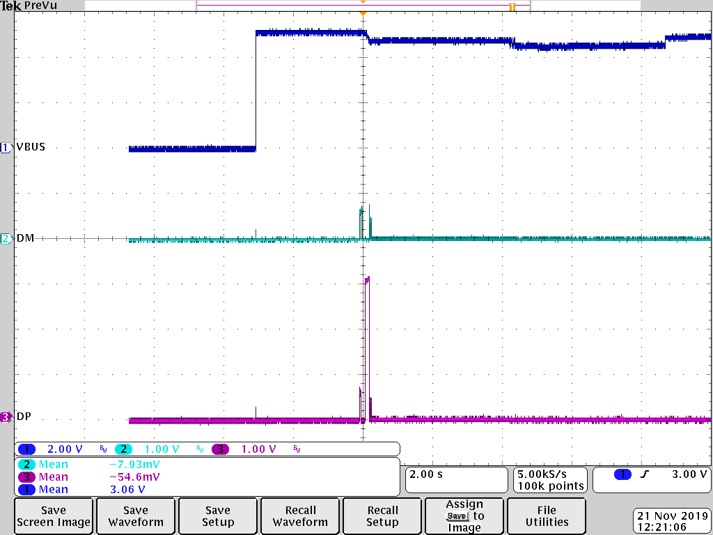
After talking with the designer:
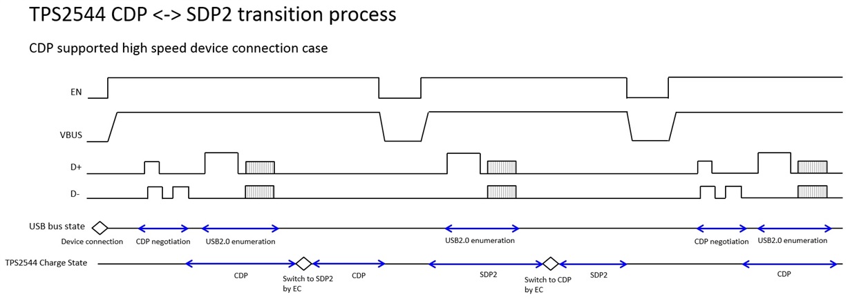
The first part of the diagram is correct. However, the DP/DM lines will not go through the second and third enumeration/negotiation highlighted in red (in the image below) after the initial negotiation when the mode is changed. The initial established data connection is seamless. The device connected will never know that the port switched from CDP to SDP2. However, if a new device is connected to the port that switched from CDP to SDP2, it will see SDP2.
To summarize:
- Device connected
- Enumeration occurs
- Mode changes
- Device does not enumerate again, and it thinks it is in the initial mode
- New device is connected, enumerates in new mode
If you look at the scope captures that I attached, even though I remove the jumper on ILIM (switching between CDP to SDP2), the DP/DM lines do not change after the initial enumeration.
Thanks,
Emma
Hello Katsuhiro,
If you are driving EN in this case, then yes this is a correct understanding. You are correct in saying that after a mode switch, the new mode will be reflected after a VBUS discharge or device reconnect.
Thanks,
Emma
Hello Katsuhiro,
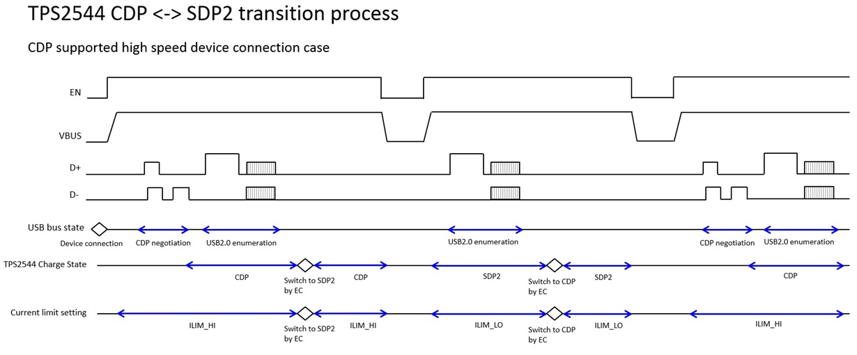
While in mode (CDP, SDP) the TPS2544 will have the current limit you illustrated here. The connected device should not start drawing current until enumeration has been completed so whether or not the current limit is applied during enumeration should not cause issues, unless you are seeing problems with the current limit during enumeration.
Thanks,
Emma