This thread has been locked.

If you have a related question, please click the "Ask a related question" button in the top right corner. The newly created question will be automatically linked to this question.

TPS2372-4EVM-006: TPS2372-4 Dual signature issue

Part Number: TPS2372-4EVM-006
Other Parts Discussed in Thread: TPS2372

Hello:

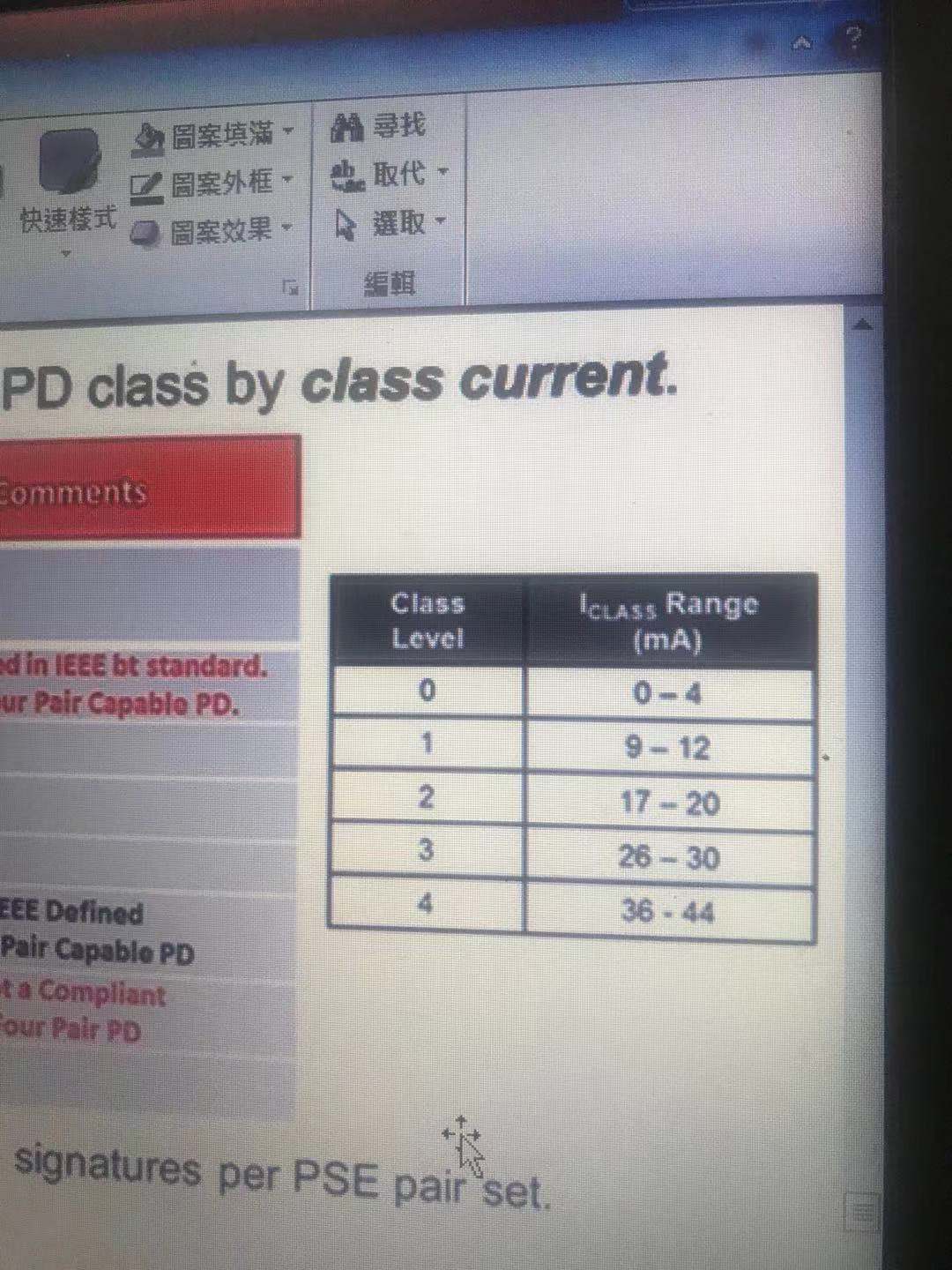
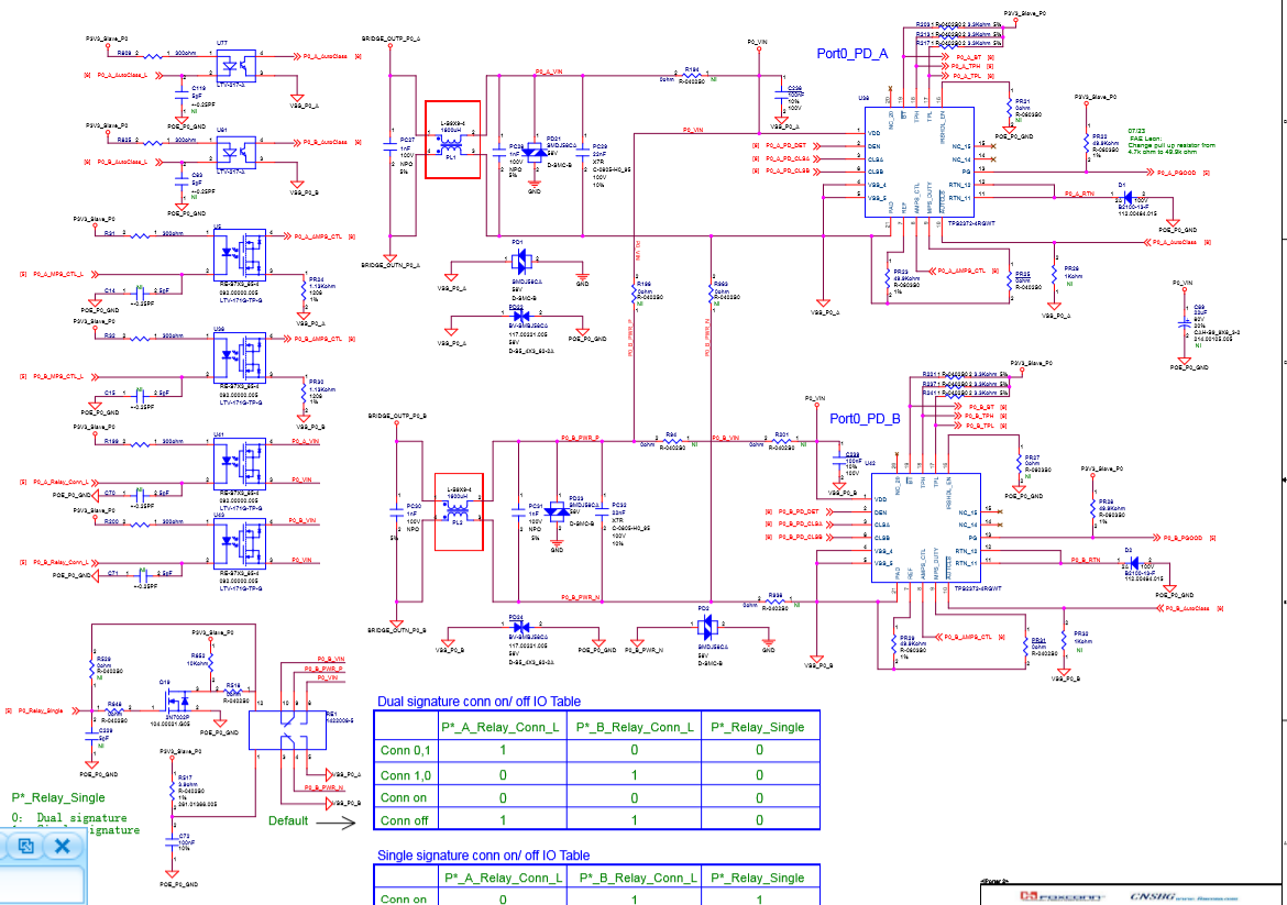
One tps2372-4 is applied to 1236 of one 4paris PSE interface, and another set of PSE 4578 pairs is used in parallel with another tps2372-4 (see figure).

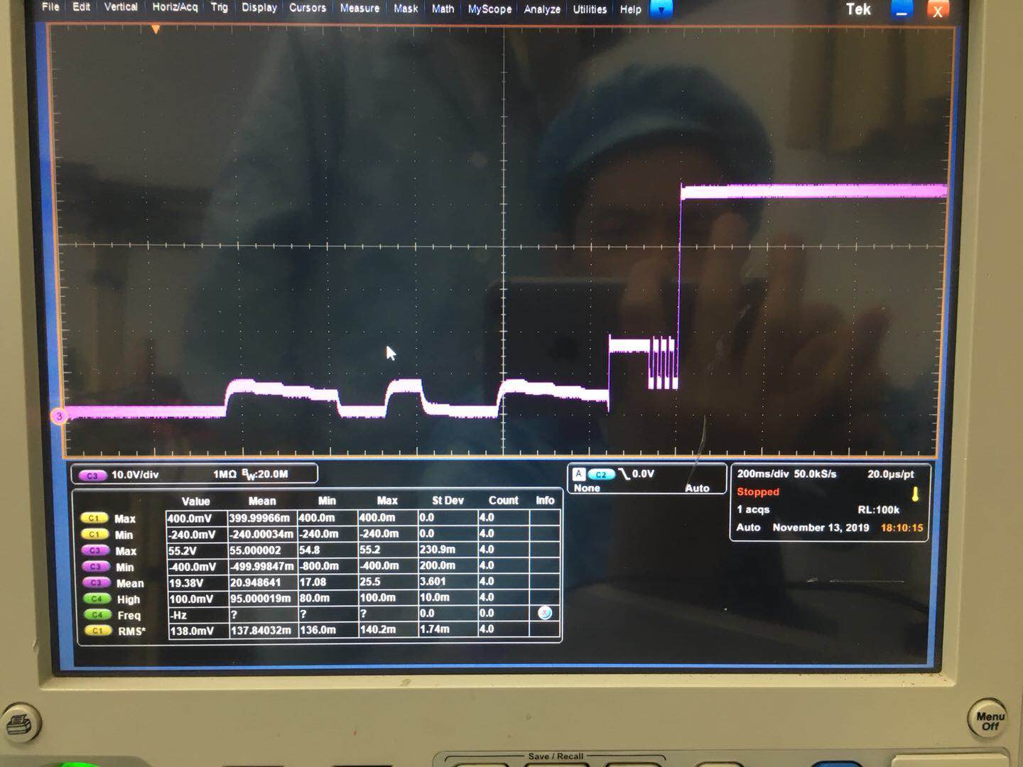
Test results: one set of identical classiflcation is successful and the other set is failed. Is there any way to solve this problem (the circuit is attached)?
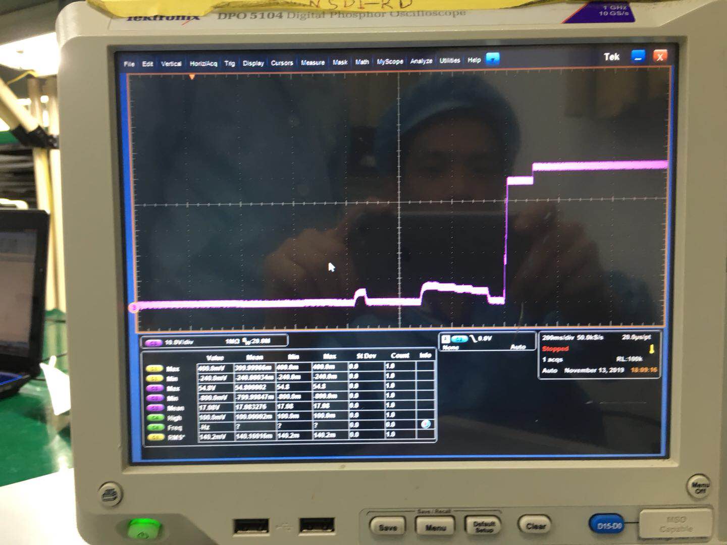
Best Regards

Leon

文晔集团

广东省深圳市南山区高新中三道9号环球数码大厦12

Mobile:(86)159 8985 2994

Tel:(86)755-26743880  Ext:6643

Fax:(86)755-26743990

  • Hi Leon,

    Are you testing with a PSE that can do .BT dual signature? When you test the channels individually (with the PDs connected) do they each show multiple fingers from the PSE. The fact that the second waveform shows that the PSE is passing detection means the PD are independently operating correctly. So this seems like either it is the PSE that's only delivering 13W on that channel or the PD is asking for Type 1 power (maybe the class resistors optos are not configured for high power). For example in a dual signature configuration CLSA should be Class 4 while CLSB should be Class 3 to get 45W on each channel (90W total from the PSE). Can you confirm this? 

  • Hello:

    Thank you for your support。 According to your suggestion, you encountered the following problems. In POE, the 20W functional output test PD is Class5.. At 15W, it was found that one TPS2372-4 PD Class4 and another TPS2372-4 PD class5. At 5W, the test found that one TPS2372-4 PD Class1 and the other TPS2372-4 PD class5..

    Best Regards

    Leon

    文晔集团

    广东省深圳市南山区高新中三道9号环球数码大厦12

    Mobile:(86)159 8985 2994

    Tel:(86)755-26743880  Ext:6643

    Fax:(86)755-26743990

  • Hello:

    Is there any way to help solve the problem of TPS2372?

  • Hi Zhao,

    Can you help clarify your debug procedure? By "20W functional" do you mean you put Class 4 resistors on each PD for CLSA and CLSB?

    Did you also confirm that the relays are operating correctly? When you set to Class 4 resistance, the relays only connect the Class 4 resistor?

    I think it will be better to first set you system up for the correct class resistors on each PD, then I recommend forcing a class voltage with a bench power supply on one PD between VDD and VSS and measure its current with a current meter. We need to verify the correct class currents can be seen by the PSE. Can you do this when one PD first, then on both (two bench power supplies with class voltage and two multimeters). Then we can see if your system solution is corrupting the current during classification.