This thread has been locked.

If you have a related question, please click the "Ask a related question" button in the top right corner. The newly created question will be automatically linked to this question.

LM66100: Reverse polarity protection with TVS diode and polyswitch

Part Number: LM66100
Other Parts Discussed in Thread: BQ35100, ESDS312, ESDS314, ESDS302, ESD351, TPS62840

Hello,

I am designing a new battery powered circuit and I need some protections on the battery connection. The battery will be a 3.6V primary lithium battery (lithium thionyl chloride).

The problem is that the battery can be changed while the system is deployed, so I want to avoid risks such polarity inversion and ESD.

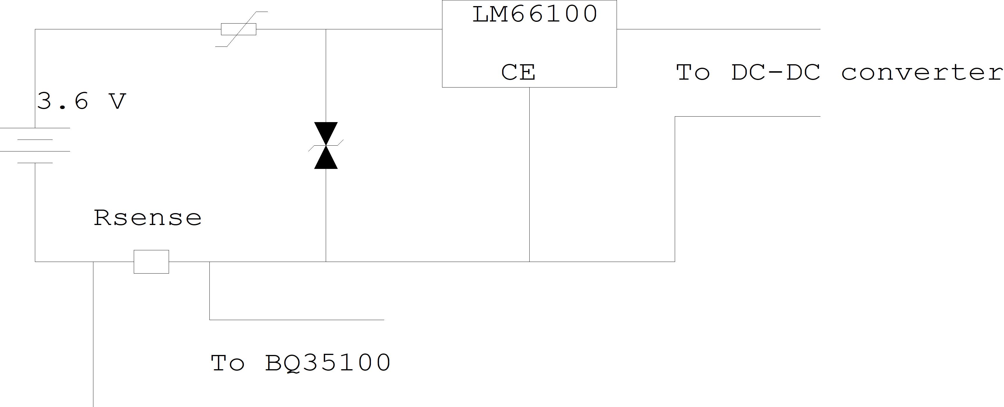
My idea is to use LM66100 to protect from polarity inversion, a TVS diode for ESD (the 2 kV ESD protection on LM66100 could not be enough...) and a polyswitch to be sure that the battery does not explode when there is some fault (TVS diodes fail short). LM66100 will be always on (CE = 0). Moreover, I have to place the current sense resistor for BQ35100.

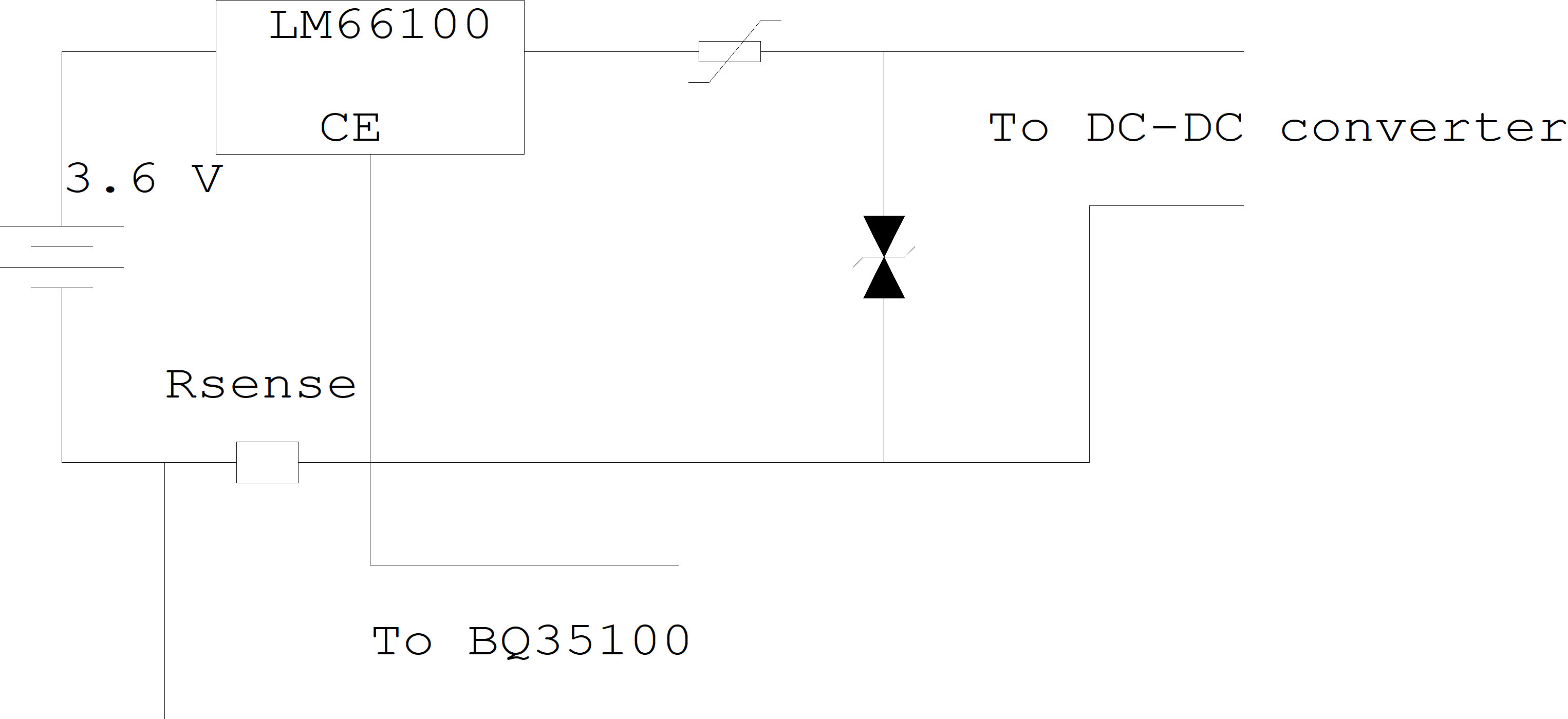
The problem is how to place all those parts. I think I should place devices this way:

But there is something not clear to me. In the case of, say, a 6 kV ESD event on the battery terminals, the TVS can dissipate power and solve the problem. But what would happen to LM66100? Could it be broken for such an event?

In general, how can I take into account the 6 V absolute maximum input voltage rate of LM66100? Perhaps shoould I move LM66100 after all devices? But this way I am not sure it can protect the circuit from battery polarity inversion.

My main goal is to have the least possible leakage from all those devices, hence I have to choose a low leakage TVS diode and a low resistance polyswitch, but how can I choose the other parameters?

Can you please give some advices about that?

Thanks in advance and best regards

Stefano

  • Hi Stefano,

    Even when turned on, there is concern for the LM66100 being able to survive the 6kV ESD stress. The maximum ESD rating is 2kV, so anything greater than this puts the device at risk. We typically see clamping (such as TVS diodes) on the input of the device rather than the output as you have drawn. This protects the LM66100 from transients while the LM66100 protects the rest of the system from reverse polarity.

    Can you let me know your concerns for reverse polarity protection when the TVS diode is on the input of the LM66100? The LM66100 will still block reverse voltage and reverse current in either condition.

    Thanks,

    Alek Kaknevicius

  • Hi Alek,

    to be honest, that was my first idea; the schematics would be as follows:

    The problem with this circuit is I cannot find a suitable TVS diode. I mean, I would need a TVS diode with a reverse standoff voltage > 3.7 V (battery voltage) and a clamp voltage < 6 V (LM66100 maximum rating), and I could not find any.

    I think there could be two ways: the first solution could be using a TVS diode with a clamp voltage > 6 V and adding a resistor to the LM66100 ground path in order to take into account the extra voltage, but this probably would prevent the reverse protection circuit to work properly.

    The second solution could be using a TVS diode with a clamp voltage < 6V, but this will have a reverse voltage < 3.7 V, so I could use a resistor in series to the TVS diode, but that resistor should have very wide ratings, and above all I am not sure it would work properly.

    So at the moment I'm stuck...

    Regards,

    Stefano

  • Hi Stefano,

    We actually may have some clamping solutions for you, but only if it is possible for the standoff voltage to be 3.6V.

    The ESDS302 and ESD304 devices are 12A surge rated dual and quad channel devices that clamp at 6V. For a 25A version, we have the ESDS314 and ESDS312.

    The ESD351 is a device rated for 6A surge in 0402 package.

    Let me know if you have any questions.

    Thanks,

    Alek Kaknevicius


  • Hi Alek, sorry for the delay but I was "absorbed" by another task until now.

    The problem with the 3.6 V standoff voltage is battery: as it has a no load voltage of 3.7 V, when the device will be in shutdown the voltage over the TVS diode could easily be over 3.6 V, so that the TVS diode will have a higher current rating. That sounds too "fragile" to me. What do you think?

    Thanks

    Stefano

    Edit: just a small upgrade: I did some tests with a battery I have here. When current is above a few milliamps, voltage on the battery drops under 3.6 V, hence the TVS diode could be ok. But when I simulate the system stand-by state (about 12 uA), battery voltage is well above 3.6 V (about 3.684 V), so the maximum operating conditions of ESD351 are exceeded with no margin, and that does not sound good to me.

  • Hello,

    What is the maximum battery voltage you will see?

    We have 5V VRWM ESD diodes that would give you more margin but do not have as low of clamping voltage.

    I would recommend that you look at our ESD training

  • Hello,

    the maximum regular input will be 3.7 V (lithium primary battery), while at the output I have a TPS62840, which has a maximum input of 7 V (clamping voltage of the ESD).

    A 5 V device should be ok, but how can I take the extra clamping voltage into account? Can I still use TPS62840 or should I change the buck converter?

    Thanks

    Stefano

  • Stefano,

    The clamping voltage of an ESD device is for very small transients as described in the training.

    I believe that the TPS62840's internal ESD structure will be able to handle >7V ESD clamping voltage.

  • Hi Cameron,

    ok for the clamping voltage. I still have some doubts about that 0.1 V at the input, but I guess it should not be a real issue, is it?

    Thanks again

    Stefano