This thread has been locked.

If you have a related question, please click the "Ask a related question" button in the top right corner. The newly created question will be automatically linked to this question.

TPS23754: How can I maximize the efficiency using flyback topology?

Part Number: TPS23754
Other Parts Discussed in Thread: PMP6812,

To whom may it concern.

Hi, I'm HS.

I've got TPS23754EVM - 383. Now I want to use it with flyback.

I happened to find the reference called PMP6812 - Class 4, Cost-optimized, Flyback Converter Reference Design for PoE Applications.

But its efficiency is quite worse than I expected and I assume because now it's quite outdated..?

So I hope I can boost the efficiency using sorta new or better components such as replacing old school diode rectifier with ideal diode bridge(MOSFET) or something like that.

To sum up, My questions are...

1. Can I boost the efficiency of PMP6812 by replacing some components? (Hopefully 90% or higher)

2. If it's quite tricky....are there any TPS23754 reference design for PoE at using flyback(V_OUT=12V) ??

3. What's the biggest difference or kinda criterion when you choose DCDC - Flyback VS Forward ?

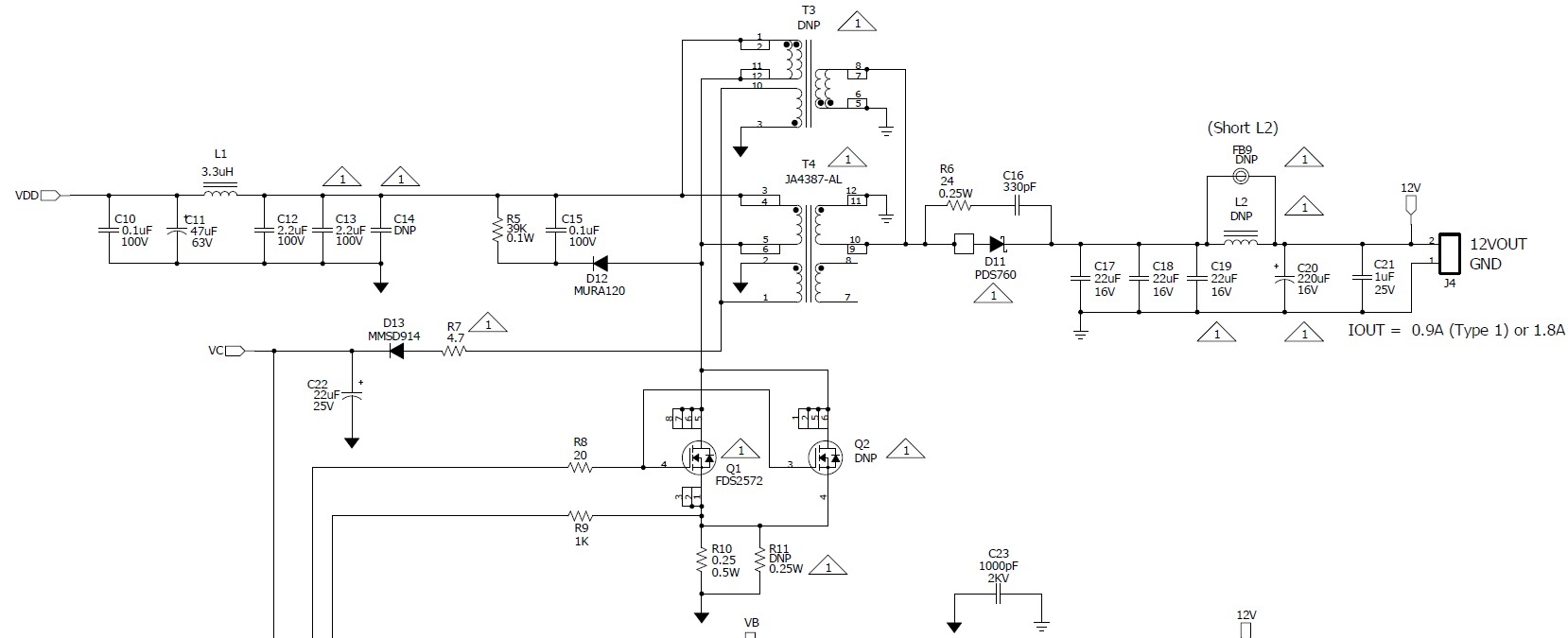
4. The schematic of  PMP6812 is quite confusing...esp because of the triangle marks.

4-1. What's the purpose of R5, C15, D12??

4-2. Would you break down the Transformer part for me?  Especially triangle marks..

5. I'm having a hard time understanding T2P section in PMP6812..esp secondary side.

Would you explain RCs on secondary side? Such as R17, R14, R15, R18, R19, C25, C26, C28 and so on??

Also, There is 0 Ohm resistor, R13. What's the purpose of this 0 Ohm?

Thank you for your hard work and I appreciate it a lot!

Hope you have a good day!

  • Hello,

    The PMP6812 is optimized for cost. The PMP6672 is optimized for efficiency,  but it is 5V/5A. 

    If I may infer, it seems that you are new to designing power electronic circuits. I want to give you some resources to aid your overall understanding:

    The TI Power Supply Design Seminar: http://www.ti.com/ww/en/power_supply_design_seminar/index-cn.html

    - this has papers, presentations and videos that explain both the basics and the innovative topics of power supply design.

    Understanding the Basics of the Flyback Converter 

    - this is a great video on how flybacks operate. 

    Here are some answers to your questions. I encourage you to check the resources provided for more information.

    1. Can I boost the efficiency of PMP6812 by replacing some components? (Hopefully 90% or higher)

    - Yes you can: http://www.ti.com/lit/an/slva475/slva475.pdf This paper describes how we took a flyback EVM and optimized it. You could follow the same process for the 12V design. 

    2. If it's quite tricky....are there any TPS23754 reference design for PoE at using flyback(V_OUT=12V) ??

    - Here is our table of reference designs. You can filter by output voltage and topology: http://www.ti.com/power-management/power-over-ethernet-poe/powered-devices/reference-designs.html#search?famid=664

    3. What's the biggest difference or kinda criterion when you choose DCDC - Flyback VS Forward ?

    - In a  nutshell, flybacks are usually 12V and can be optimized for cost, Forwards are usually 5V and can be optimized for efficiency. Those are very general statements, but that is typically how it happens. 

    4. The schematic of  PMP6812 is quite confusing...esp because of the triangle marks.

    -The PMP6812 has type 2 and type 1 options which require different BOMs. The white triangles indicate if a component would be changed. 

    4-1. What's the purpose of R5, C15, D12??

    - this is a clamping circuit 

    4-2. Would you break down the Transformer part for me?  Especially triangle marks..

    - It is important to note there are two transformers here. One is populated for the 12V version, one is populated for the 5V version. DNP means do not populate. 

    The black triangles are primary ground. The white triangles are same as above. 

    5. I'm having a hard time understanding T2P section in PMP6812..esp secondary side.

    T2P is a part of the IEE802.3 standard for PoE. A power supply unit may not power the device with the power it requested (ex. may only send 13W instead of 25W). T2P lets the circuit know if it is receiving higher power or not, and should b e used to adjust the circuit to handle the difference. 

    Would you explain RCs on secondary side? Such as R17, R14, R15, R18, R19, C25, C26, C28 and so on??

    - This is the feedback network of the circuit so that the controller knows how to adjust the output. 

    Also, There is 0 Ohm resistor, R13. What's the purpose of this 0 Ohm?

    - if you were to do a bode pot to check stability you would exchange the 0ohm for a 50ohm. But if you are not, keep it 0 ohm. 

    Lastly, I encourage you to look at our training videos for PoE to introduce you to the technology. 

    https://training.ti.com/power-over-ethernet-poe-training-series

    Regards,

    Michael Pahl