This thread has been locked.

If you have a related question, please click the "Ask a related question" button in the top right corner. The newly created question will be automatically linked to this question.

TPS63000: Start problem

Part Number: TPS63000
Other Parts Discussed in Thread: TPS63070, TPS63050

Hi,

20% of my boards do not properly start. I use a PS (3.67V) with serial resistance to simulate a battery.

80% of my boards starts even if the serial resistance is 20ohms (10ohm is my requirement), but 20% of the boards require less than 2ohms to start.

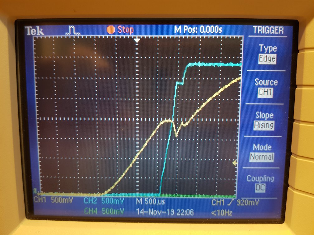
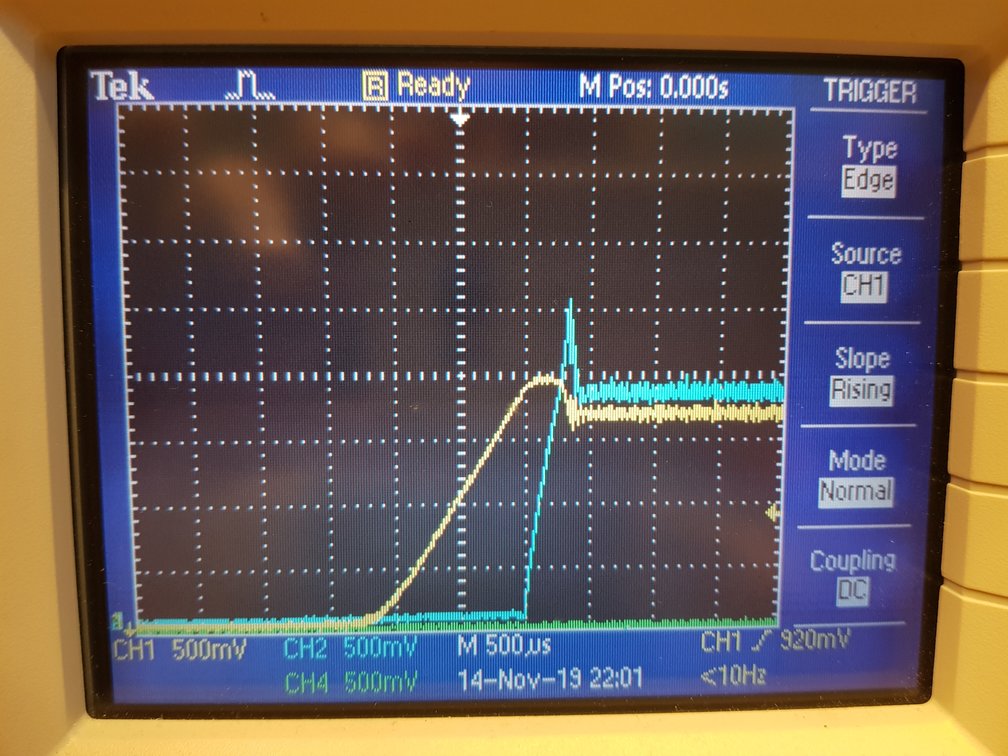
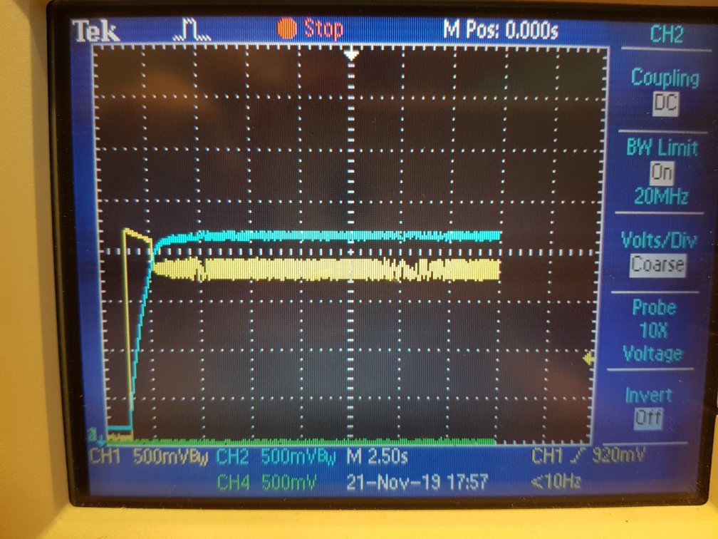
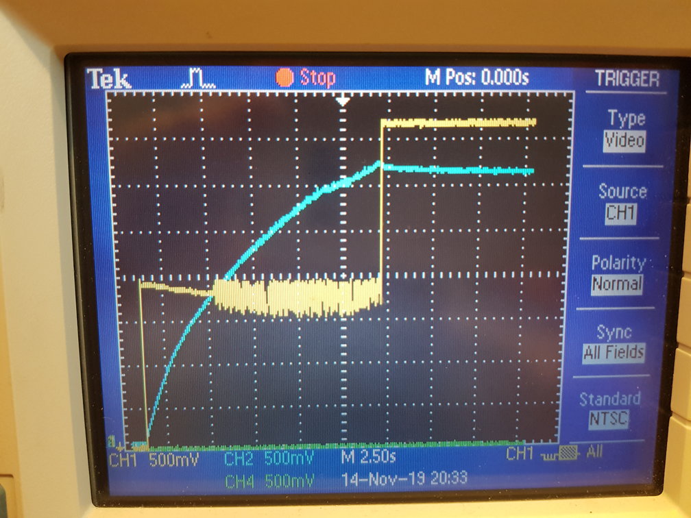
Below shows problem at 10ohms, YEL=Vin, BLU=Vout

Starting

NOT Starting

Regards

CHA

  • Hi CHA,

    This can happen when using DC/DC converters with high inrush current. The inrush current causes too large voltage drop due to power supply resistance, which then triggers the UVLO and turns off the device. The input voltage then recovers and this cycle repeats itself. Eventually the converter can start up after some time (like in your first image), or it can get stuck in startup (like in your second image). 

    If you cannot reduce the resistance of your power supply (I guess this is limited by the battery you want to use), you can try reducing the inrush current. One way to do it is shown in this application note:

    http://www.ti.com/lit/an/slva307b/slva307b.pdf

    This specific note is for the TPS63070, but the same can be used for the TPS63000. 

    Best regards,
    Milos

  • Hi Milos,

    Many thanks for your promt reply.

    As far as I understand the slva307b soft start deals with high inrush currents due to the output load (like a high value capacitor). The TPS63070 DS specifies maximum output C to 470uF.

    However I have selected the TPS63000 due to its unlimited capacity for output upper capacitance. My load is a 0.5 Farad capacitor. 
    I am not saying the soft start circuit you propose is wrong, but I would like to be more certain before I go ahead and do hardware design changes.

    Below you can also find 10 ohm behaviour when the 0.5F C is disconnected (only load is a 22uF capacitor). Still 20% of the boards do not start (unless Rbatt<2ohm), while 80% of my boards have no problems at all, even when Rbatt is increased very much (its does however take longer time to start for increased Rbatt)).

    It is such a distinct difference! Either there is no problem to start (even with very high Rbatt) while other boards require well defined low Rbatt (<2ohms) to start. 
    If the problems were related to UVLO, I would expect a more "spread out" behaviour of my boards.
    Could the problem be related to manufacturing issues, or possible a bad TPS63000?

    Unloaded, starting

    Unloaded, not starting

    Regards

    CHA

  • Hi Milos,

    I have now tested 50 boards from another batch, all perfectly starts. But the Vin start waveform is a bit different (see below). The 50 pcs boards also have TPS63000 from a different batch.

    50 pcs board TPS63000 marking "BPT 87K D3EQ"

    80% ok boards TPS63000 marking "BPT 91K CTLH"

    20% failing boards TPS63000 marking "BPT 91K CTLH"

    Startup waveforms below. YEL=Vin, BLU=Vout

    50 pcs board all starting TPS63000 marking "BPT 87K D3EQ".
    Up to Vout=2.7V the load is identical for all boards (charging of 0.5F C). Final load for this boards is 20mA.
    The final load of the below boards are 30uA (thats why Vin ends up higher for the below boards).

    80% ok boards starting TPS63000 marking "BPT 91K CTLH"

    20% failing boards not starting TPS63000 marking "BPT 91K CTLH"

    Any idea?

    Regards

    CHA

  • Hi Milos,

    I forgot to mention, for all waveforms in this post the PS voltage is 3.67V and the series resistans (Rbatt) is 10 ohms.

    Rgds

    CHA

  • Hi CHA,

    Thanks for the additional info. 

    The waveforms from your 2nd batch look more what I would expect. For the whole first batch, the input voltage looks too clean in the beginning.

    But in any case, this is the startup issue caused by high source impedance. The operation when the device oscillates around UVLO is something we cannot characterize, some devices might recover, some will not. If you look at the datasheet, figures 18 and 19, the inrush current for Vout = 3.3 V will be more than 1 A, and the UVLO will be triggered if Rbat>(Vbat-Vuvlo)/Iinrush which is in your case around 2 Ω.

    What can help in this case is:

    • Enabling the device after the input voltage supply is turned on and the input voltage is settled (delayed enable),
    • Enabling the load only after the output voltage is settled.
    • Adding the above mentioned soft-start circuit which will slow down the output voltage ramp-up, and reduce the inrush current. 

    If this doesn't help, then a device with programmable soft start needs to be used.

    Best regards,
    Milos

  • Hi Milos,

    Thanks for your advice. I will try to figure out what way to go (which might need "trial-on-error" via several routes).
    However, I think I have faced a fundamental problem:

    Every Switch mode regulator, regardless of application, are likely to be exposed to Vin oscillating/switching around UVLO.

    - If the operation around UVLO is not characterized, I do not understand how I shall ensure start of regulator, regardless of trial-on-error results.
    Even if I change to a regulator with programmable soft start I can not be sure how it should be programmed, unless the regulator behaviour around ULVO is specified. 

    Is it possible for you to exactly specify the criteria(s) that guarantees start of the TPS63000?

    Can you recommend any other regulator for my application?

    From the Data Sheet I can read the following:

    "The TPS6300x devices provide a power supply solution for products powered...by Li-polymer battery" [page 1].
    - I use one of the most common Li-polymer cells (Li-SOCl2).

    "The controller circuit also senses the average input current as well as the peak input current. With this, maximum input power can be controlled as well as the maximum peak current to achieve a safe and stable operation under all possible conditions." [page 7].
    - My TPS63000 is not stable as it oscillates around ULVO.

    "During start-up of the converter, the duty cycle and the peak current are limited in order to avoid high peak currents flowing from the input." [page 8].
    - Peak currents, even if not high, causes my locked condition where the regulator does not start.

    "At an output voltage of about 1.2 V, the current limit is at its nominal value. If the output voltage does not increase, the current limit will not increase. There is no timer implemented.Thus the output voltage overshoot at start-up, as well as the inrush current, is kept at a minimum. The device ramps up the output voltage in a controlled manner even if a very large capacitor is connected at the output." [page 9].
     - My output voltage is above 1.2V, but stucks at 1.85V. The output voltage does not ramp up to 3.3V in a controlled manner even when I have a 0.5 Farad load.

    "There is also no upper limit for the output capacitance value. Larger capacitors causes lower output voltage ripple as well as lower output voltage drop during load transients." [page 12].
     - I expect the TPS63000 to have no problems at all to start regardless of upper value of output capacitance. However, the problem I see also applies for only 22uF of load.

    "The TPS6300x devices have no special requirements for its input power supply." [page 15].
    - I have a typical source impedance of a Li-SOCl2 single cell.


    From above information, taken from the TPS63000 data sheet, I did expect the TPS63000 to be a perfect choice. It has also been recommended by TI FAE. 

    What is your feeling about that the start problem I have reported might be due to faulty TPS63000 or manufacturing problems?


    Best Regards
    CHA

  • Hi CHA,

    user4867287 said:

    Every Switch mode regulator, regardless of application, are likely to be exposed to Vin oscillating/switching around UVLO.

    - If the operation around UVLO is not characterized, I do not understand how I shall ensure start of regulator, regardless of trial-on-error results.
    Even if I change to a regulator with programmable soft start I can not be sure how it should be programmed, unless the regulator behaviour around ULVO is specified. 

    Is it possible for you to exactly specify the criteria(s) that guarantees start of the TPS63000?

    Can you recommend any other regulator for my application?

    Normally, the safest way to start up the converter is to let the input voltage settle before enabling the converter. This way the input capacitor will be fully charged and can better support the inrush current, and avoid triggering the UVLO. And here, a larger bulk capacitor helps.

    In your case, you are turning on the converter while ramping up the input voltage. If the source impedance is sufficiently low, this might also be fine, since UVLO always has some hysteresis to avoid oscillations during turn on (for the TPS63000 this should be around 200 mV). But if the source impedance is too high, oscillations cannot be avoided.

    To guarantee a proper start of the TPS63000, the source impedance should be low enough or the input capacitance high enough not to trip the UVLO due to inrush current. The external circuit that I mentioned previously also helps since it slows down the output voltage ramp-up, and reduces the inrush current.

    user4867287 said:

    From the Data Sheet I can read the following:

    "The TPS6300x devices provide a power supply solution for products powered...by Li-polymer battery" [page 1].
    - I use one of the most common Li-polymer cells (Li-SOCl2).

    "The controller circuit also senses the average input current as well as the peak input current. With this, maximum input power can be controlled as well as the maximum peak current to achieve a safe and stable operation under all possible conditions." [page 7].
    - My TPS63000 is not stable as it oscillates around ULVO.

    "During start-up of the converter, the duty cycle and the peak current are limited in order to avoid high peak currents flowing from the input." [page 8].
    - Peak currents, even if not high, causes my locked condition where the regulator does not start.


    Thanks for pointing this out. We should make a note here that a too high input impedance might prevent proper startup, regardless of the battery type.

    user4867287 said:

    "At an output voltage of about 1.2 V, the current limit is at its nominal value. If the output voltage does not increase, the current limit will not increase. There is no timer implemented.Thus the output voltage overshoot at start-up, as well as the inrush current, is kept at a minimum. The device ramps up the output voltage in a controlled manner even if a very large capacitor is connected at the output." [page 9].

     - My output voltage is above 1.2V, but stucks at 1.85V. The output voltage does not ramp up to 3.3V in a controlled manner even when I have a 0.5 Farad load.

    "There is also no upper limit for the output capacitance value. Larger capacitors causes lower output voltage ripple as well as lower output voltage drop during load transients." [page 12].
     - I expect the TPS63000 to have no problems at all to start regardless of upper value of output capacitance. However, the problem I see also applies for only 22uF of load.


    Here, the problem is that even though the current limit is limited to some value, it is still to high for the power supply to provide proper input voltage.

    user4867287 said:

    "The TPS6300x devices have no special requirements for its input power supply." [page 15].

    - I have a typical source impedance of a Li-SOCl2 single cell.


    Here again we should make a note about the input source impedance limitation.

    I can try powering on the device with increased input capacitance, with inrush limiting circuit, and a 0.5-F supercap on the output to give you some guidelines for the component values and if startup is possible for battery impedances above few Ω.

    Alternatively, we have the TPS63050 which has similar specs and package as the TPS63000, but also has programmable inrush current limit that could help here.

    Best regards,
    Milos 

  • Hi Milos,

    I already use a 100uF input capacitor. I will see what happens when I increase it even further.

    I have tried to charge the input capacitor to 3.67V before enabling the TPS63000, but the start problem remains.

    You plan to make a note about possible problems with high source impedance. Before you do that I would like to emphasize that batch TPS63000 marked "BPT 87K..." do start with very high source impedance.
    Please have a look at the below graph, where Vbat is 3.67 V and Rbat is 20 ohms! As you can see it perfectly starts, but it takes of course longer time. This behaviour has been verified with several hundreds of boards.

    The second graph shows a no-start with TPS63000 marked "BPT 91K...". In this case Vbat is 3.67 V and Rbat is reduced to 3 ohms.

    A well defined difference between the different TPS63000 batches (?) is that Vin is smooth until regulator enters boost mode for batch "BPT 91K".  While Vin directly (also in buck mode) starts "oscillate" with batch "BPT 87K". The latter batch is the one that works fine.

    With this big difference (20ohm_start / 3ohm_No_start) in behaviour, how can you be sure that the problem is not due to a bad batch of TPS63000?
    I am asking, so I do not go ahead with hardware changes before other realistic root causes are excluded. If hardware changes are required I will run into design problems, since I do not know how much future batches of the TPS63000 will deviate from what I will use during design verification.

    Regards
    CHA

    Batch 87K, starting with 20 ohms.
    10 sec/DIV, YEL = Vin, BLU = Vout

    Batch 91K, Not starting with 3 ohms.
    2.5 sec/DIV, YEL = Vin, BLU = Vout

  • Hi CHA,

    To be honest, I would still be slightly hesitant to rely on the device recovering from oscillations around the UVLO, even if having a statistically significant sample of a few hundred units. After manufacturing the device, during the automated testing, we don't test for startup under high source impedance. If this is the only case the device doesn't start up properly, we could not detect that, and that device would pass the test system.

    We cannot be sure that the problem is not due to a bad batch, but just want to first verify and confirm the issue, and using the startup-test-under-high-impedance is not something we consider to distinguish the failing device. But there might be another problem making this difference between the devices.

    Have you seen any other difference with the failing devices beside the startup issue?

    Otherwise, you can always start the customer return process by following the guidelines and info here:
    http://www.ti.com/support-quality/additional-information/customer-returns.html
    http://www.ti.com/support-quality/additional-information/failure-analysis.html

    Best regards,
    Milos

  • Hi CHA,

    I tested seven TPS63000EVM boards we had, at Vin = 3.6 V, Vo = 3.3 V, with different input resistances, without a load. Three couldn't start with input resistances above 4.7 Ω, while three could start even with 20 Ω. The last one could start with 10 Ω. All these devices passed the standard production tests, and they all oscillated during startup, just like on your latest scope plot. Depending on the input resistance, they either get stuck or they recover after some time. 

    The only safe way in these situations is to avoid UVLO oscillations completely, and there are 3 ways to do this:

    1. Using the external startup circuit like i showed in my first reply. Selecting the worst device (which doesn't start with 4.7 Ω, starts with 2.2 Ω), and adding a 22-µF capacitor in the soft-start circuit, and 0.5-F supercap on the output, the device started without oscillations:


      The soft start circuit limits the slew rate of the output voltage, so it takes some time to reach 3.3 V. This is an indirect way to limit the input current during startup. 
    2. Limiting the input current directly, as described in this application note:
      http://www.ti.com/lit/an/slva912/slva912.pdf
      This is more costly than above, however.
    3. Using a device with a low enough input current limit. Our TPS63050 has programmable current limit, however still not low enough to work with 10 Ω input resistance under above condiotions without triggering the UVLO. 

    Hope this helps.

    Best regards,
    Milos

  • Hi Milos,

    Based on your answers I will waive faulty batches of TPS63000, as the root cause of the start problems.

    I think I will go ahead with hardware changes, according your proposed way no 1.

    Thanks for your support.

    Best Regards

    CHA