Because of the Thanksgiving holiday in the U.S., TI E2E™ design support forum responses may be delayed from November 25 through December 2. Thank you for your patience.

This thread has been locked.

If you have a related question, please click the "Ask a related question" button in the top right corner. The newly created question will be automatically linked to this question.

REF102: REF102 + OPA227 Precision Current Source Issue

Part Number: REF102
Other Parts Discussed in Thread: OPA227, , OPA277

Dear member of this forum,

I need to generate a very precise 10 uA current .

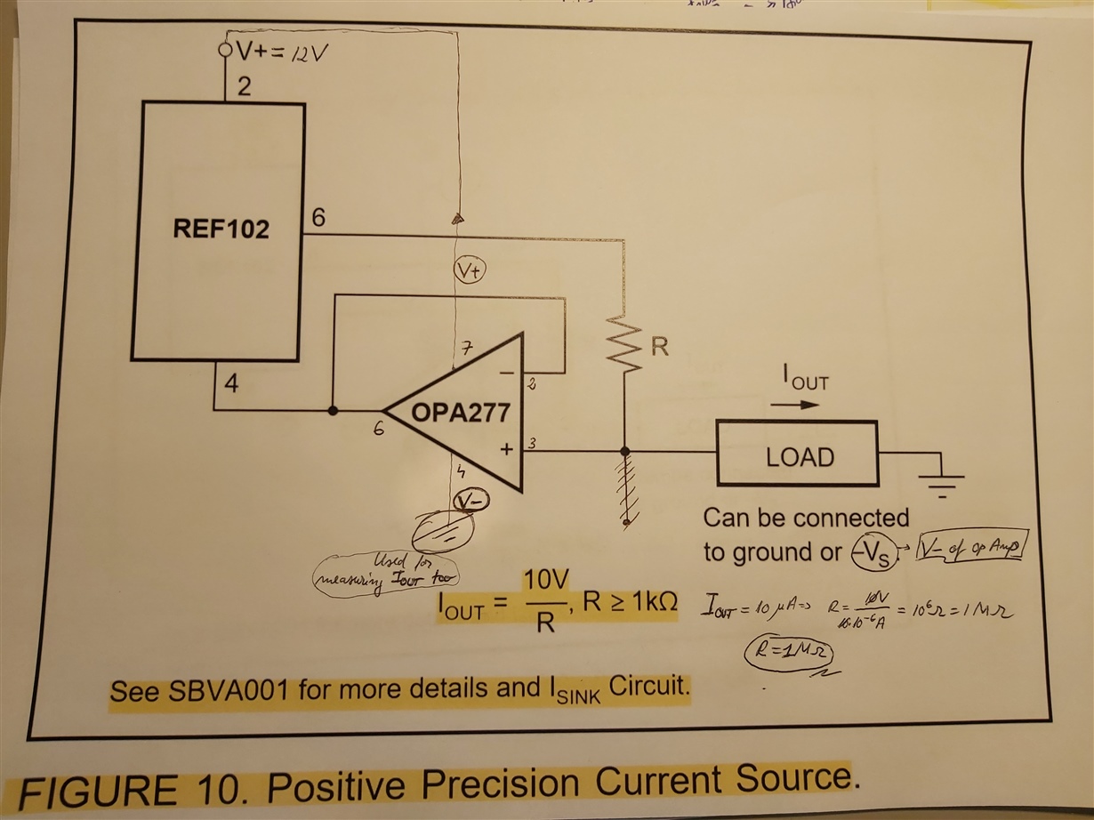
I used the schematic in the description of the REF102 chip together with the OPA227 Op Amp.

Additional to the schematic I also supplied the Op Amp ( V+ Pin of Op Amp ) with 12V.  As ground for the whole circuit I used the V- Pin of the Op Amp (for measuring the resulting current too).

Please see the schematic I attached to this post.

Here is the issue : When the Op Amp is supplied with voltage the voltage on the resistor falls from the expected 10V to 1.5V. Also the Op Amp gets hot !

I checked the breadboard for short circuits. I also checked for mistakes. On YouTube there is a tutorial with the exact same setup and there it did work !

Still... I used a SOIC Package OPA227 together with an adapter to use it on a breadboard. Maybe is the SOIC Package too sensitive to 12V ?

Any suggestion would be highly appreciated !

Thank you for your time and I am looking forward for your answers !


  • HI user,

    How much precision do you need on the current source?

    What are the voltages at each of the pins?

    By resistor are you referring to the load or the resistor R on the datasheet?

    What is your current load?

    -Marcoo

  • Hello Marcoo,

    - I need 10 uA with a precision of  +-1 nA (actually 0.001%)

    - I did not measure the voltages on the pins. The REF102 is supplied with 12V. The OPA227 also with 12V.

    - You are right... I was not clear enough. The 10V are on the resistor R from the Datasheet. For measuring the 10 uA current I didn't use an external resistor or load (I assumed the multimeter as having an internal one ). I also tried with a random resistor as load...but still the same problem occurs.

    - Current load (I_out on the schematic) is no near the expected 10 uA. It is somewhere around 400 uA. When I supply the OPA227 with 12V, I_out suddenly turns in approx. 1uA.

    Thanks for your interest in my issue. I am still waiting for some suggestion. And I am sorry for answering so late !

    Feel free to ask me anything else.

  • I believe I found the video you are referring too by EEVblog.

    I can't debug the circuit completely through E2E. I have ordered the REF102 and OPA227 samples and they should arrive late this week.

    If you can provide me the exact schematic, I can test it on my bench 1:1 to see if i can replicate the issue.

  • Hello !

    Exactly, it is the video from EEVBlog which inspired me to try the layout from above.

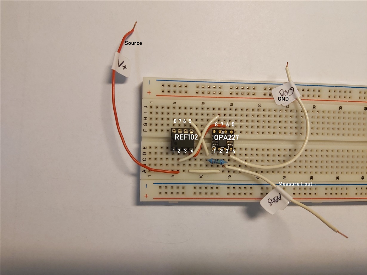
    If it helps, here is a Photo with the circuit itself !

    Don't let yourself tricked by the adapter for the OPA227 ! The pin numbering is exactly as for the REF102.

    Hopefully it helps !

    Thank you once more for taking interest in my issue !

  • Hi,

    My REF102, OPA277, and OPA227 arrived. This circuit works well with both devices.

    Can you swap the OPA227 for a different OPA227 or a OPA277?

    Can you Seperate out the supply pins? The OPA227 does not need the full 12 volts

    I feel yours might of been damaged.

  • Hello !

    I have tested the OPA227 alone and it really gets hot at 12V.

    Probably is the package of the OPA227 itself that causes the issue.The SOIC Package that I've used is definetely smaller than the PDIP Package. As a consequence it is probably too sensitive at 12V... In the Datasheet the maximum supply voltage for OPA227 is rated at 36V.

    Could you have a look at the photo above and see if the circuit that I've built is ok ?

    I have ordered the PDIP OPA227 that should come next Thursday.  I will definetely try again with smaller voltage on the OPA227.

    I will definetely come back with a feedback next week !!

    Thank you once more !

  • Your circuit matches my circuit in wiring. It worked with the OPA277 and so when you receive yours, it should work as well.

    I used your image to build mine to keep it as similar as possible.

    Keep us updated when the new units arrive.

  • Hello again !

    I tried with the new bigger OPA227 and it works perfectly. Even by supplying with 12 V !

    IN CONCLUSION : The SOIC Package does not take too high voltages such as 12V. The PDIP Package on the other side manages 12V without problems.

    Thank you once more for your support !