This thread has been locked.

If you have a related question, please click the "Ask a related question" button in the top right corner. The newly created question will be automatically linked to this question.

LM3445EVM-695: Q&A

Part Number: LM3445EVM-695
Other Parts Discussed in Thread: LM3445,

Dear all:

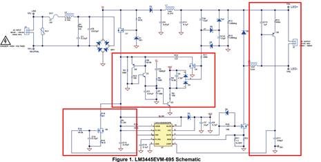
       1,We have a line lamp project requirement, and we are going to use LM3445 to do it.I have seen TI's lm3445evm-695, and I think this circuit is relatively complex. Can you explain the functions of each circuit in the DEMO (the position of the red box is drawn)?

2,The capacitance of lm3445evm-695 is 22uF.If the grain filling capacitance increases, does it affect the output?There is a formula for the relationship between capacitance and output voltage and current

3,The output dimming line lamp power is not the same (such as: a total of three line lamps in parallel, the output voltage is 42V, the current is 160MA, 320MA, 480mA), what should LM3445 do to ensure the dimming depth of three lamps consistent?

Thank you!

  • Hello Timsen,

    1)  The circuit to the right is for the off-timer.  The PNP translates the current to a ground referenced current to charge the Coff capacitor.

    The circuit in the lower left is used to add loading to the rectified AC when the dimmer is set for lower light output.  This keeps current flowing in the triac so it doesn't misfire.

    The circuit in the middle does two things.  The portion tied to the valley fill capacitor adds loading when the valley fill capacitors start supplying the LEDs.  This is because the loading from the rectified AC goes away and the triac needs current flowing to stay on.

    The second circuit is for reverse phase/trailing edge dimmers.  It detects a falling edge dv/dt and adds loading to discharge the capacitors across the line and across rectified AC.  If there is not enough loading the capacitors hold the voltage up causing a false angle sense reading that is too wide.  This causes the current to ramp up which in turn causes the angle sense duty cycle to drop.  It will oscillate this way indefinitely.  Enough loading for the trailing edge dimmer prevents this.  If you are not going to use these types of dimmers that circuit could be removed.

    2)  It can.  They are sized to be as small as possible while providing enough voltage to run the buck converter.  This is because Power Factor will drop when these capacitors go up in value (for a fixed output power).  There is a method to calculate this it requires quite a few variables, Vin minimum, Vled, Iled, and line frequency.  It is simply calculating 1/2 of the minimum AC input voltage (which will be the DC valley fill voltage after subtracting a few diode drops).  The energy it needs to supply during the time the AC is below 1/2 of the peak voltage which, for 60 Hz is approximately 2.8 ms.  When the triac is involved this time will go up and depending on the dimmed current level a bit more capacitor may be needed.  The easier method is to try it under all operating conditions and see what the capacitor headroom is by watching the valley fill voltage and LED voltage.

    3)  There will always be slight differences in each circuit.  Fortunately at deeper dimming levels the LM3445 goes discontinuous giving the dimming at low levels more resolution.  As for more lamps attached.  If the circuitry keeps the triac functioning as it should the output of the triac shouldn't change much with the number of lamps attached.  Even if it changes some the user will not know unless they have an elaborate method of switching bulbs in and out when the dimmer is on.

    Best Regards,