This thread has been locked.

If you have a related question, please click the "Ask a related question" button in the top right corner. The newly created question will be automatically linked to this question.

UCC28950: pmp8740 shim inductor heating

Part Number: UCC28950

Hi,

To achieve ZVS I have used shim inductor. PQ2620 core AF139 material, 33SWG conductor 30 strands, inductance 50uH.

And it is noticed that the shim inductor is heating a lot it is going beyond 100 degrees in a few minutes. I have tried at 400W as well as at 800W.

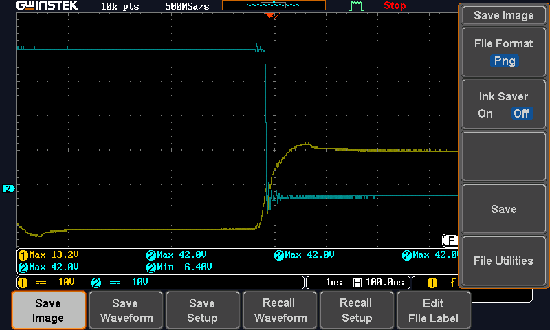
initially, I thought it is due to the minimum load issue for zvs. But the thing is that heating is increasing as loading got increased. Attaching the Vds and Vgs waveforms at 800W load.

blue is Vds(10X probe) 400V, yellow is Vgs. I think the miller plateau is still present. which means ZVS is not achieved. the case is almost similar for both the active and passive legs for 800 and 400W loads.

What will be the reason for this?

  • Hi Nidheesh,

    It could be a couple of things.

    1. power dissspation in the windings, measure the winding resistance and calculate the I^2 * Res loss in the winding. Note that the AC resistance will be higher due to skin effect and proximity effect. But it will give you a good first estimate.

    2. Core loss, I cann find the AF139 material on the Web, we normally use 3F3, 3C96, or 3C95 materials. Please check peak flux levels by calculation to ensure the core is not saturating. You should also calculate the power dissipation in the core at the flux level of operation and frequency.

    If the shim inductor saturates then there is only a low value of inductance in the resonant tank and ZVS may not be possible.

    Regards

    Peter

  • Hi Peter,

    thank you for your response.

    Actually core name was CF139 not AF139 ..sorry..

    When I was using the conductor of 21SWG and 2 strands heating was severe. But 35 SWG 30+ strands heating got reduced but still heating.

    Can you say anything about ZVS from the attached graph?

    Actually gate pulse is a bipolar signal, so w.r.t common zero graphs attached. as per the graph, Gate pulse is getting positive only after VDS became zero. So is this correct ZVS. Or we have to look into the first graph? ( Both graphs are the same, But in second both have common 0V)

    So can you judge anything on the ZVS from this?

  • Hi Nidheesh,

    Thanks for pointing out that the gate drive voltage is bipolar.

    If the Vds voltage across the device has collapsed to zero before the gate voltage has risen to the Vgsth then you have ZVS.

    In the waveforms above it looks like ZVS as the Vds voltage has fallen to 0V  and the gate voltage is just transitioning through 0V.

    Regards

    Peter

  • Hi Peter,

    Thank you for your valuable replay.

    Now can you please say what was the max temperature in your shim inductor(in your evaluation board). It is very difficult to get the same part that you used.

    Is that is having airgap between the cores?

    Is there any isuue if I am using gapped cores to avoid heating due tocsatuarion?

    Regards

    Nidheesh.

  • Hi Nidheesh

    I'm afraid I don't know what the temperature of the shim inductor on the EVM is.

    If the inductor is getting hotter as the load current increases, then the increase will be due to copper losses because the core losses would remain more or less constant.

    Assuming you have designed your shim inductor to run at 100kHz and with a flux swing of 200mT then the CF139 core material will have a power loss of 400kW/m^3. The PQ26/20 core has a volume of 5820mm^2 and this gives a core loss of 2.3W. Assume a similar loss in the copper for a total close to 5W. Please check these numbers.

    Anyhow, the shim inductor does not have a DC current in it so a gap is un-necessary. If you have no gap then the permeability will be close to the ui value in the material data sheet or about 2100. The Al value of the PQ26/20 is 7020nH*T^-1 so you would need only about 3 turns to give 50uH.

    Take a look at the information and procedures in the documents at

    https://www.ti.com/seclit/ml/slup304/slup304.pdf

    and https://www.ti.com/seclit/ml/slup132/slup132.pdf

    Regards

    Colin

  • Hi Colin,

    With Litz wire I was able to reduce heating little bit.

     So issue is seems to be from the core material that I have purchased. So now I tried with differnet material from another manufacturer. Now heating is almost under control.

    But it is noticed that R98 is heating. What is the purpose of this R98?

    (my Output voltage is 60V and Vds of secondory MOSFET is found to be around 180V)

    Regards

    Nidheesh

  • Hi Colin, 

    I have read an article in which u described how to calculate R98 value. So in that, you are calculating 1/2 L/N I^2 for leakage inductance w.r.t secondary.

    I have Shim inductance of 10uH as leakage if so do I need to add this also to the calculation of 1/2 L/N I^2 or only transformer leakage inductance need to be considered?

  • Hi Nidheesh,

    Sorry for the delay but Colin is out of the office this week, he will be back next week and can answer then.

    I did look for R98 in the UCC28950 EVM but I did see it in the BOM?

    Regards

    Peter

  • Hi Peter,

    Here I am attaching the schematic.R98 is marked with a red circle.

  • Hello Nidheesh

    The resistor R98 forms part of the secondary snubber network along with the capacitors C64, C74, C75, C76. The capacitors will be charged through D13 by the high speed spikes on the transformer secondary waveform and the purpose of the resistor is to form a discharge path to Vout.

    Regards

    Colin

  • Ok, Colin.

    Thanks