This thread has been locked.

If you have a related question, please click the "Ask a related question" button in the top right corner. The newly created question will be automatically linked to this question.

TPS40210 audiable noise when dynamic load

Other Parts Discussed in Thread: TPS40210

Hi

I am using TPS40210 for a 5V->12V non-isolated converter, when I doing the dynamic load test (1KHz, load_high: 1.3A, load_low: 0.01A, 50% duty), audiable noise can be heard, may be from inductor. Can some one help me to remove this noise?

The design requirements are:

VIN: 4.75V~5.25V

VOUT: 12V

IOUT(MIN): 0.01A

IOUT(MAX): 1.3A

Following is the schematic:

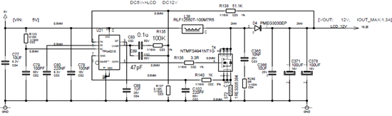
Switching frequency is about 330KHz, Paramter of the components are:

Inductor: 10uH, 7.5A(max); CHF: 47pF; CFB: 0.1uF; RFB: 100Kohm; RIFLT: 1K; CIFLT: 220pF; Output capacitors: 10uF ceramic + 200uF OS capacitor (16SVPC100M, SANYO) ;

Input capacitor: 10uF ceramic + 220uF OS capacitor.

When adding static load (0A to 1.3A, any value), everything are OK: no noise, ripple voltage is very low (less than 200mV);

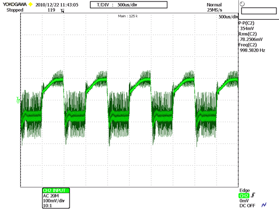
But when adding dynamic load, noise came out; ripple voltage increase a little, about 360mV. Picture of ripple voltage is attached below:


Thanks in advance.

  • Cai Changzuo,


    It is highly likely that you are generated the audiable noise because you are stimulating the circuit at 1kHz, which is a highly audiable frequency.  Your waveforms don't show any instability issues or audiable noise conserns other than the fundemental load frequency noise.


    1) Check your inductor to make sure it's mechanical design is sound.  Inductors have the same basic construction as an eletromagnet or selenoid - A magnetic core with an electric wire wrapped around it.  When you apply a current to the coil, you generate a magnetic field, which also applies a mechanical force between the coil of wire and the core.  If the coil or wire are free to move (even slightly) they can generate noise.  As a result, any magnetic component (inductor or transformer) that will be exposed to audiable frequencies (20Hz - 20kHz) should be constructed to prevent movement between the coil and the core.  They may require a varnish or other mechanical finish to the constructed inductor or transformer.

    2) Check the mechcanical attachment of the inductor to the PCB.  Just as the coil and core could be moving with respect to one another, they could be moving with respect to the PCB.  The mounting of the inductor should eliminate any movement of the inductor with respect to the PCB.  This may mean adding additional mechanical mounting, such as adhesives, sealants or even post assembly conformal coating.


    If you want to check to see if the noise is a result of the pulsed current or the supplies response to the pulsed current, you could also connect a microphone up to an oscilloscope and measure the frequency of the generated noise, but I strongly suspect that it's 1kHz  and a result, not of power supply design, but the pulsed load you're applying to the system.

  • Hi Peter

    Thanks very much for your help.

    The frequency of noise should be same as the dynamic load, as I when changed the load frequency, voice changed.

    I once calculated the compensation value according to datasheet, but with these values, the efficiency is very low and ripple voltage is high. Then I tried a lot of values, change components and found that 100K+0.1uF is the best one. I don't konw whether the noise has some relationship with this compensation circuit.

    Now I added 330uF aluminum capacitor on the output, noise almost dispeared. But the problems is I can't add more capacitor on the PCB as PCB size limited.

    Merry Christmas.

  • I don't konw whether the noise has some relationship with this compensation circuit.

    The compensation value changes the controllers response to the dynamic load, affecting the amount of ripple generated at the ouptut based from the load step, so yes, the compensation can affect the noise.

    change components and found that 100K+0.1uF is the best one.

    What components did you change?  It sounds like you've implemented a dominant pole compensation loop with a 10ms time constant or about 300Hz bandwidth, which will result in the converter averaging the 1kHz load steps, allowing the output capacitor to smooth the output voltage and this would reduce the audiable noise generated by a inductor.

    Now I added 330uF aluminum capacitor on the output, noise almost dispeared. But the problems is I can't add more capacitor on the PCB as PCB size limited.

    The additional output capacitance is providing hold-up to the load.  At 1kHz, the load step is about 500us.  This would further reduce the bandwidth and average the inductor current through the steps.