This thread has been locked.

If you have a related question, please click the "Ask a related question" button in the top right corner. The newly created question will be automatically linked to this question.

LM2776: Charge pump does not the good output volatge?

Part Number: LM2776

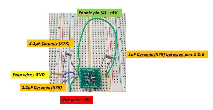
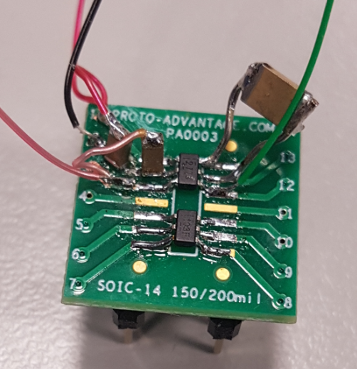
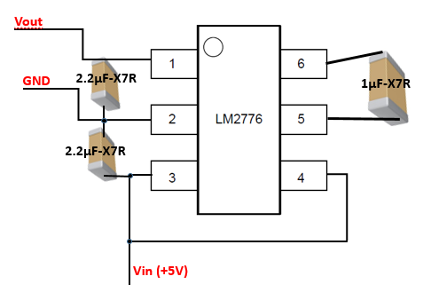
I don't have a power rail of -5V in my circuit I used the LM2776 charge pump to obtain it using the +5V power rail available in my circuit. The LM2776 is not outputting the -5V that I was hoping for. The first output voltage is around -2.72V

Then and after switching ON/OFF of the Input power supply, the output volatge down lower and not exceed 372mV!!. I followed the typical application of the LM2776 datasheet (http://www.ti.com/lit/ds/symlink/lm2776.pdf) using the same capacitor value.I don't put any charge on the output!

Could you please help me!

  • Hi Sadok,

    could you please give me some more information with regards to your application:

    1) Could you please share your schematic with me?

    2) Could you send oscilloscope plots for the input and output voltage?

    3) What has been changed between the scenario where you see -2.72V at the output and 372mV?

    4) Are you using the LM2776EVM?

    5) What is your load condition?

    Thanks and best regards,

    Britta

  • Hello Britta,

    Please find below my answers :

    1) Could you please share your schematic with me?

    2) Could you send oscilloscope plots for the input and output voltage?

    I did not take curves

    3) What has been changed between the scenario where you see -2.72V at the output and 372mV?

    I switched OFF the Input voltage, and then switched ON! The Consumption on the + 5V reached 67mA !!

    4) Are you using the LM2776EVM?

    No I using the LM2776DBVR (samples from TI)

    5) What is your load condition?

    I do not have any load on the output

  • I can understand why you'd want to use a breadboard, but this necessarily breaks all of the guidelines in section 10 of the datasheet.

    If you don't want to design a custom PCB, you still have to put the capacitors as near the pins as possible; solder them directly on the legs of the LM2776.

  • OK I see, but what is the explanation about the consumption (more 67mA) on the power supply (+5V) and without load?

  • All the energy is lost in the parasitic resistances, capacitances, and inductances of the breadboard/traces/wires.

  • We have applied the requirements with capcitors mounted near the component. But we have alwyas the same behiavour as such a high consumption without load : 68mA under +5V and the output voltage is around 370mV!! We think regarding the figure19 in the datasheet, that the switchs S2 and S4 are ON always!! that mean the INput voltage is connect to ground!!

    Question, could you please confirm that the pin configuration regarding the datasheet and the picture of the sample, it's same? otherwise, could you confirm that pin1 is located on right top of the picture?


    Many thanks

  • The pin configuration is correct, and the same as on the EVM.

    Can you check with an oscilloscope if the device is actually switching?

  • Please, could you explain how to process? Could you send us a drawing for to understand what we will do?

    Many thanks

  • Unfortunaly, we have no chance! Indeed, we have 5 samples of the LM27776 (lot N°8068809NFM) but none don't work!! After switch ON, nothing in the output and the supply current (on +5V) is too high (around 68mA!!) so, The component becomes non-functional because we find strangely a connection between pins 5 (+C) and 2 (GND) ?

    Could you please share with us any explanation to understand that?

    Could you check if the batch (lot) is good?

    Many thanks

  • Hi Sadok,

    you mentioned that you now mounted the capacitors closer to the IC. Could you please share an updated picture and - if possible - also send a drawn schematic of your connections. I'd also recommend to check the connections with a multi-meter or oscilloscope to make sure the pins are connected to the desired signals.

    In order to understand the behavior you are describing, could you please explain to me how you measure the output voltage and current consumption and confirm the measurements with oscilloscope plots?

    Please explain how you measured the connection between Pin 2 and 5.

    Note that even if the current situation can be clarified and the device works to a certain extent it will not operate at expected/ best performance using a breadboard.

    Best regards,

    Britta

  • Hi Britta,

    The capacitors closer to the IC.


    A drawn schematic of my connections.


    Also recommend to check the connections with a multi-meter or oscilloscope to make sure the pins are connected to the desired signals.

    ==> done and it's okay

    In order to understand the behavior you are describing, could you please explain to me how you measure the output voltage and current consumption and confirm the measurements with oscilloscope plots?

    Output voltage = not more 370mV!!!

    Power Supply Current = 68mA ???

    I have not taken any oscilloscope plots

    Please explain how you measured the connection between Pin 2 and 5.

    ==> After that we observed the over consumption (around 68mA on +5V Input power supply), we test by multimeter the connexion between pin 5 (C+)  and 2 (GND), and there is a contact between the both pins ==> it's a normal process regarding the following detailed schematic in the datasheet ==> we suppose that switch S2 is colsed and the connection between GND (pin 2) and C1+ (pin 5) and S1 is closed too ==> so a short-circuit between Vin and GND!! The voltage output do not exceed 370mV!!

    Note that even if the current situation can be clarified and the device works to a certain extent it will not operate at expected/ best performance using a breadboard.

    ==> The circuit does not work whatever the configuration ?? So is this a batch problem of components? could you check please?


  • Hello Britta,

    Do you have the time ta analyse and study my answers. Do you have answer about the inegrity of the batch, because it is not possible to have the same problem with 5 pieces while the wiring has been done correctly and the checks also!

    Please advice

  • Hi Sadok,

    Please kindly share oscilloscope plots so that I can see your input voltage, output voltage and output current.

    Also please kindly describe where in your circuit to take the measurements and with which equipment.

    I would like to rule out that this is connected to a setup problem. Please also confirm the voltage at EN pin.

    Thanks and best regards,

    Britta

  • Dear Britta,

    Could you please explain why the values of input and output capacitors are different between the datasheet and the eval board? Indeed, these capacitors are 2.2µF in the datasheet, but are 10µF in the eval board. In added, for wihch reason, there are 2 parallel capacitors on input side?

    We have tested the eval board and we have constated that for output currents lower than 40mA, ripples of a few tens of mV were observed on the output voltage. We added a LC filter (680μH / 33μF) to attenuate the max these ripples (about 2mV).

    So, we hope tested again the component (LM2776) as the same configuration as the eval board (LM2776EVM) to confirm the results.

    Best regards

  • Dear Britta,

    Could you please send me the Altium Library (symbol and footprint) of the LM2776DBVR (DBVT).

    Many thanks

  • Hi Sadok,

    please have a look at the following link and instructions:

    https://www.ti.com/product/LM2776/pinout-quality

    Best regards,

    Britta

  • Hello Britta,

    The CAD/CAE symbols don't an answer for my request. Indeed, I need of the librairie (Symbol + footprint for PCB) of the component for Altium Designer.

    Thank you for your answer

  • Dear Britta,

    Do you have any answer about the integrity of the lot of the 5 samples of the LM27776 (lot N°8068809NFM)? Because we don't understand why none part is functional.

    Could you check if the batch (lot) is good?

    Many thanks

  • Hi Sadok,

    did you check the instructions next to the CAD/CAE files? Those should help you generate files to be used with Altium.

    Best regards,

    Britta

  • Hi Sadok,

    I have checked with our quality team and we have not seen issues with the lot you mentioned. 

    This does not seem to be a systematic issue on chip side but rather application specific.

    As far as I understood you've evaluated the EVM of the device and it worked fine. You could try to swap the ICs you're using on your board and place them on the EVM to confirm functionality.

    Besides, I'd still like to ask you to provide oscilloscope plots.

    Thanks and best regards,

    Britta

  • Hello,

    Yes I apply the steps, but in finally I obtain this window with theimpossbility to generate the schematic symbol and footprint of the LM2776DBVR.

    Could you check please?

    Many thanks

    Sadok

  • I will try with a new batch and hoping to obtain best results!

    Many thanks

  • Hi Sadok,

    you should be able to download the Altium files from the Ultra Librarian website, however you will have to create an account there.

    As I said before, there was NO issue with the lot you've received parts from.

    I'd suggest to have a further look at the circuit. Could you provide oscilloscope shots of the input and output rails as a start?

    In case you don't feel comfortable in sharing those Publicly I suggest to take this discussion offline.

    Best regards,

    Britta

  • Hi Sadok,

    I will go ahead and close this thread here.

    I sent you a separate request to further discuss this via e-mail, as we will need to look into the oscilloscope plots of your application to understand the different signals and further dig to understand the issue.

    Best regards,

    Britta