This thread has been locked.

If you have a related question, please click the "Ask a related question" button in the top right corner. The newly created question will be automatically linked to this question.

BQ76200: The DSG wave Oscillation in the load condition

Part Number: BQ76200
Other Parts Discussed in Thread: BQ76940

Dear All:


  condition as below:

   the Pack Voltage  13S  === 48V

   the   electronic load      ===  13A

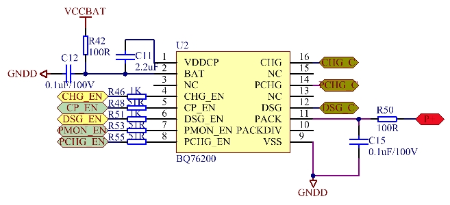
  the BQ76200 Schematics  as below 


   the Pack  connect the  electronic load, when i set the  BQ76940 DSG to turn on the MOS,   the BQ76200 DSG out  pin  waveform  is  oscillates as below picture 1,

   the Blue waveform is  the  MOS wave

  the yellow waveform is the  DSG Wave

 the red waveform is the current wave


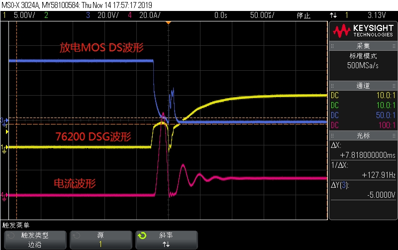
         if i connect the capacitors in parallel at the  electronic load  with 2200uf/100V, the oscillates will disappear as below picture2

         can you  explain what cause the results? Thanks.


  • Hi Bill,

    Please see http://www.ti.com/lit/pdf/slua794. With 48V and the electronic load I expect the output may be rising so quickly that the ESD cell may trigger as shown in figure 11.  The 100 nF capacitor C15 is too large for the PACK pin, it needs to be able to follow the P+ more closely for proper operation.  The electronic load may have a response time to start to regulate, the voltage may be able to rise before the load comes on suddenly.  Capacitors on the output are present at all times and may be allowing current to build slowly giving better response in this case.  The electronic load will likely have capacitors at its output, you may need to check its manual to determine if they are always present or if they are switched with the load.

    I would suggest decreasing C15 to the 10 nF recommended (or smaller) so that PACK can better follow P+.  Add the zener and 100 ohm between DSG and PACK pins to avoid internal losses if DSG rises quickly, and consider adjusting R40 larger to optimize turn on.  Don't make R40 too large since it also affects turn off. 

    You will likely need to adjust C12 also, again 10 nF is the recommended.  For very dynamic battery voltages you may need a smaller value so the BAT can better follow the changing B+ voltage.  

  • Dear  WM5295:

       Thanks for your  help, can you explain  why I add the  the capacitors  with 2200uf/100V in parallel at the  electronic load, the  waveform oscillates will disappear.  

  • Hi Bill,

    I don't know why the 2200 uF capacitors would remove the oscillation.  The capacitors will be present in the system at all times when connected while the load will switch with its response time based on the input it receives.  This may excite the circuit differently.  Some equipment has specific recommendations for terminating long cables.  It can be a challenge to determine how to test your system in a way which represents how it will be used.