This thread has been locked.

If you have a related question, please click the "Ask a related question" button in the top right corner. The newly created question will be automatically linked to this question.

TPS2378: SLVU682 User's Guide | GND

Part Number: TPS2378

Hello,

I'm trying to design a PD device with the SLVU682 User's Guide in reference.

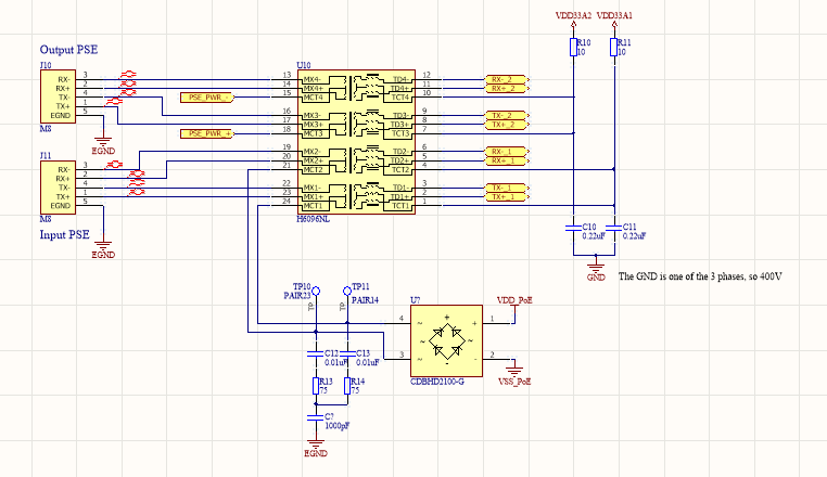
My question is about the GND near C11 and C12 in the schematic on page 4 of this document

Are they the same GND ?

Moreover, i can't understand the relevance of the resistance R1, R2, R3 and R4. Can anyone help me about this ?

Finally, do we agree that the circuit, after the DC/DC, must be isolated  ?

Thank you in advance.

Matteo Baldi

  • Hello Matteo,

    The GND near C11 and C12 is considered to be Earth Ground. Yes they are the same ground and should be connected.

    The resistors are in place to be Bob Smith terminations to the cables to provide surge protection for the circuit. 

    Here are some papers that discuss that topic in length: https://www.ti.com/lit/an/slvae50/slvae50.pdf

    http://www.ti.com/lit/an/slua736/slua736.pdf

    The circuit after the DC/DC does not have to be isolated. Buck converters are used in PoE. However, the application may require isolation, so my point is PoE may be isolated or non-isolated, depending on the application. Typically, I would recommend isolation.

    Regards,

    Michael Pahl

  • Hello Michael,

    Thank you for your quick reply. I'm going to isolate my application.

    Do you know a simple way like a chip to do so ?

    Best regards,

    Matteo

  • Hello Matteo,

    Isolating a design does not come from a chip, but from the fact that the ground planes are physically isolated on the board. We typically use either a flyback or a forward topology for isolated applications. 

    A great place to start is our reference design library where you can look through our designs, and filter them on isolation, power, output voltage and more:

    http://www.ti.com/power-management/power-over-ethernet-poe/powered-devices/reference-designs.html#search?famid=664

    Regards,

    Michael Pahl

  • Hello Michael,

    Thank for all your informations and your time but I have one more question.

    My application mesure the power of a three phase device. I use one of these phase like my ground, so 400V.

    So, the ground of my Ethernet communication will be at 400V and these wires will be connected directly to the coil (T1 in the schematic). 

    I would like to know if it will be a problem or not ?

    I hope you have an idea for this.

    Best regard,

    Matteo

  • Hello Matteo,

    Can you clarify with a block diagram how you plan to do this? Is the voltage differential or common mode?

    To clarify, the PoE standard voltage max is 57V, and our parts are rated for 100V. So applying a 400V differential signal between VDD-VSS would damage the parts. 

    Regards,

    Michael Pahl

  • Hello Matteo, 

    Any update on this post? 
    We have not heard from you in almost a week. If we do not hear anything in the next 48hours I will assume the issue is resolved. You can post here to open the thread if the 48 hour time passes before you are able to answer. Thank you for your interest in TI PoE products.

    Regards,

    Michael Pahl

  • Hello Michael,

    First, I would like to apologize my late response. Below, my schematic around the audio/signal transformer : 

    I have to do like this because it simplifies the diagram of the sensor. Ethernet data is connected to a switch (LAN9313-NZW) with the following schema : 

    This GND is the same as the first schema. So my question is : 

    Is inside the audio/signal transformer (H6096NL), the GND will be a problem ? 

    I hope my explanations are clear and thank you for taking time for that !

    Regards,

    Matteo Baldi

  • Matteo,

    Thank you for the clarifying pictures. The IC has a reference labeled RTN. Keep this ground separated from GND pictured above. The 400V GND should be isolated from the rest of the board with Bob Smith Planes / Terminations. 

    Additionally, just making sure the input transformer can handle the voltage on the lines along with the capacitors connected to the ground. Otherwise this should be okay. 

    Regards,

    Michael Pahl