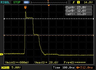
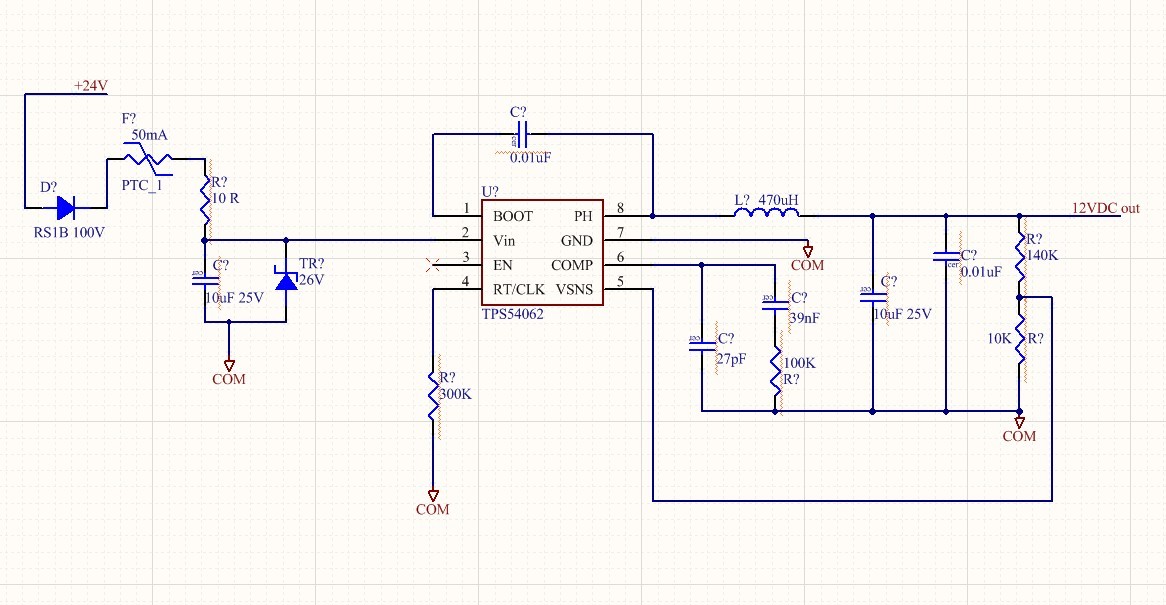
I have a sensor pcb using the 54062, based on a design from the switcher program done approx 4 yrs ago. A linear reg was not considered due to a 20mA max input spec.
Other spec's:
Vin, 24V,
Vout, 12V,
I out 25mA, load current similar to resistive, negligible inductance nor chance for surging backward to output.
We have installed about 4K of these in the past 4 yrs with almost no failures in the first 2 years. Conversely, there have been what I would call an excessive number of failures in the last 2 years' production. Exact figures n/a yet, but ballpark is 3-4%. Failure modes I've seen (in descending order of occurrence) are:
-high input current, input clamping to 0.6-0.7V. Bypassing the PTC simply overheats/fries the IC in seconds, (majority, dozens)
-predictable input current (twice normal 14mA) , output full 'ON', 23V output (twice normal, hence current input) ~6
-negligible input current, output voltage near 0.8V, no output on PH pin, ~4
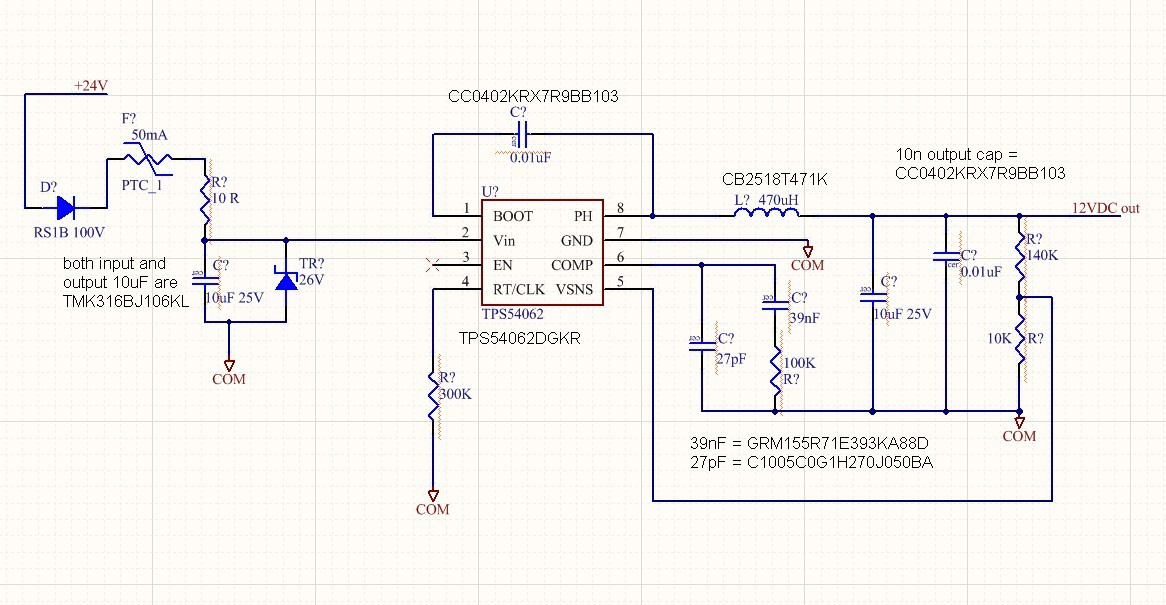
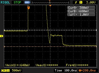
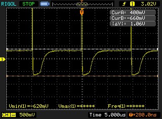
-(rarely happens) negligible input current, output voltage near 0.3V, switching output on PH pin as seen in 3 scope captures attachmented (very low duty cycle pulses at rep period ~20uS.)
Any idea how I might figure out what happened here? The input TVS has a max clamp voltage of around 44V, so it seems like it should prevent the input seeing >60V. Any suggestions welcome, but the pcb seller
has said he wants to ditch this IC immediately, dropping the 20mA max in to rely instead on a linear part.
-