This thread has been locked.

If you have a related question, please click the "Ask a related question" button in the top right corner. The newly created question will be automatically linked to this question.

BQ25570: what is the minimum and maximum current, that can be handle by BQ22570 from Battery to system load

Part Number: BQ25570
Other Parts Discussed in Thread: BQ25505

As shown in Block diagram of BQ25570, Battery and system load can be separated.
As in user guide of BQ25570, on Page 3 para 1 line 5th states that:
"In general, the storage element also allows the system to handle any peak currents that can not directly come from the input source."

1) What is the minimum and maximum current, that can be handle by BQ22570 from Battery to system load? 

2) Is BQ25570 is capable of providing below requirement?

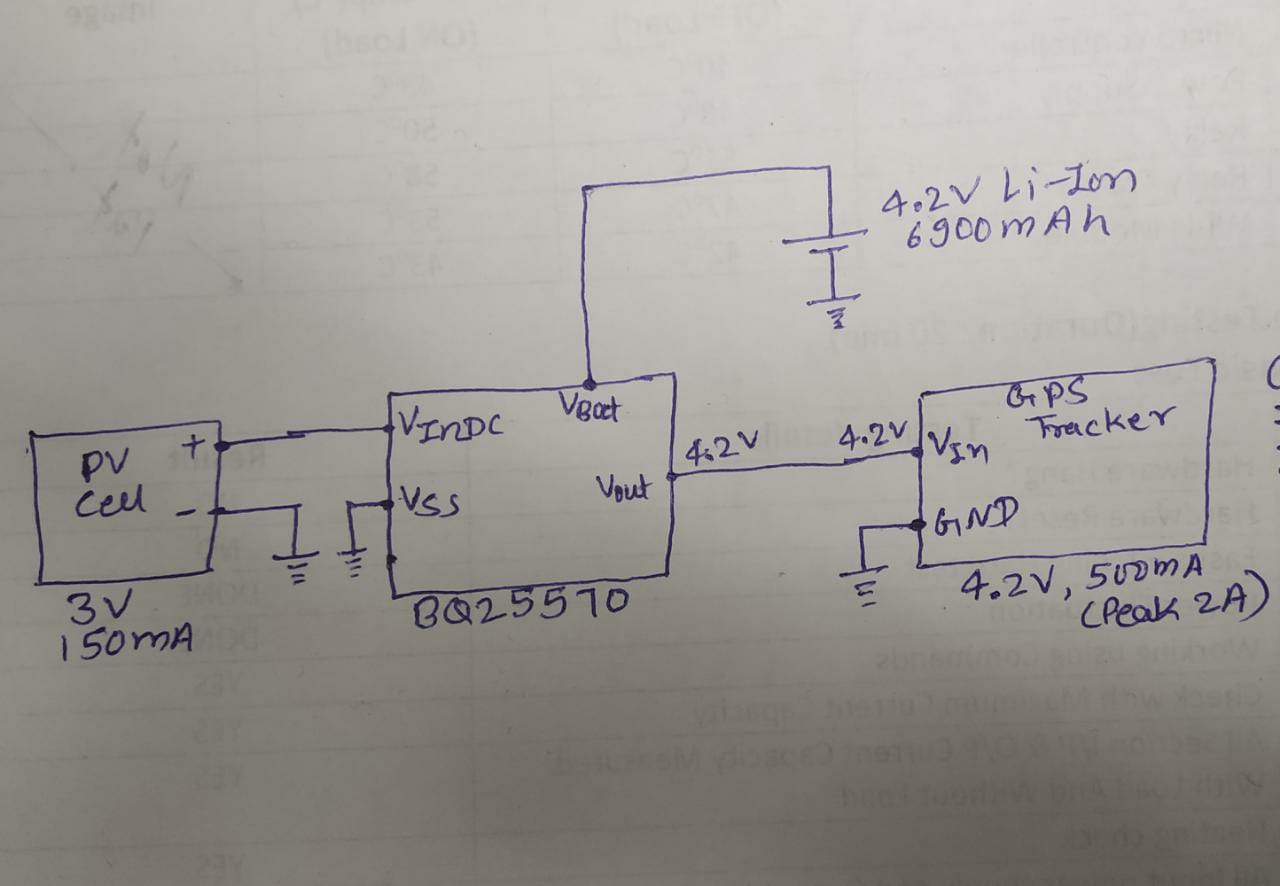
Our system GPS Tracker specification is as follow:
Input Voltage: 4.2V mostly (3.7V-4.2V)
Current consumption: 500mA when running
Solar Capacity: 3V 100mA
Battery Capacity : 4.2V 6900mAh Li-Ion Battery
Block Diagram is as follows:

  • Dipakkumar,

    The regulated buck output can only support a peak output current of 110 mA. It is designed for very low power peripherals such as sensors or MCUs that require lower voltages (think 3.3V or 1.8V logic) and very limited current. 

    I am a little confused about your VOUT setting. The charger is designed to boost up the input voltage the charge the battery and buck down the charge voltage to produce VOUT.  You say your VOUT is set to 4.2V, but 4.2V is also your charge voltage. This is problematic because as your battery discharges, the voltage will fall below 4.2V. In these situations you would get no output from VOUT as it cannot buck the voltage down.

    I do see a potential solution in putting the GPS tracker in parallel with the battery. This would allow you to meet you 500 mA (2A peak) requirement as the current would flow directly from the battery to the tracker. What is the minimum voltage the GPS tracker requires to operate?

    Thanks,

    Ricardo

  • Dear Ricardo,

    Thanks for well response.
    Our GPS Tracker system can be operated in range of 3.7V to 4.2V.

    Would you please take this values in your consideration and provide solution for it, again?
    And If We didn't use Vout and use system directly with battery, then what would be schematic scene at Vout.

    We also have a 5v 150mA Solar Plate, Is this IC is suitable for this Solar?

    Thank You 

    Dipakkumar Bhutada

  • Dipakkumar,

    I think a better choice for your application would be BQ25505. I have provided some possible thresholds for your resistor divider network. Please review Figure 12 in the datasheet to understand the meaning of these thresholds. Once understood, use this calculator to calculate appropriate resistor values for your circuit. 

    This IC is intended for use with solar panels and a 5V open circuit voltage is suitable, but please note that this IC is a boost battery charger. This means that when VIN_DC is greater than VSTOR the converter will not operate and current will be sunk from VIN_DC to GND via an internal MOSFET. For deeper analysis of how much power your solar panel will provide and what kind of operating life you can expect from this circuit I suggest you look at this solar panel calculator.

    Thanks,

    Ricardo