This thread has been locked.

If you have a related question, please click the "Ask a related question" button in the top right corner. The newly created question will be automatically linked to this question.

LDO noise with very light loading

Other Parts Discussed in Thread: ADS8326, TPS7A49

Hi-

I'm trying to design a system with a 16 bit ADC.  While the op amps in the circuit are good, the ADC has little to no power supply rejection.  So my understanding is that the power supply needs to be quiet to at least 16 bits.  If the input range into the 16 bit ADC is 0 to 5V, each LSB step is 76uV.  Thus the noise on the power rail needs to be less than (5 / 65536) = 76uV.  I am finding it almost impossible to reach this goal.  The noise is comprised of 3 different things.  First, semiconductor noise, second noise passing through the LDO from the line side, and third, noise caused by load current variations.

The product is battery powered and I am trying to design this for as low an operating current as possible.  I am using ultra low power op amps and they are all using less than a few hundred uA.  I am using an ADS8326 ADC.  This converter is on only for the duration that it samples and data is read out on the SPI.  Then it goes back to low power.  It varies between several mA when operating to 0.1uA when powered down.

I have tried LP2992-5.0, LP2985-5.0, LT1761-5, various TPSxxx LDO's and even the new TPS7A4901.  All of these parts seem to have really poor load regulation when they are operated with very, very light loads.  For example look at the datasheet for the TPS7A4901.  Its specification for load regulation is 0.04% of Vout.  If it is set for 5V for example, 0.04% of 5V is 2000uV.  This, is much worse than 16 bit "quietness".  Looking at Figure 17, the curves for load regulation at several temperatures, the problem looks pretty obvious at the very left edge of the graphs.  Between about about 5mA of load current and 0, the output voltage varies by a lot more than it does over almost all of the rest of the range from 5mA up to 150mA.  So far, the only fix I have found is to put a resistor between the output and ground that draws a continunous load current of somewhere between 5 and 10mA.  But this then is not super low power.

Anyone have any thoughts?

Can anyone explain why this is so?  I have read through slva072.pdf and don't really see an answer there.

Thanks!

-Randy

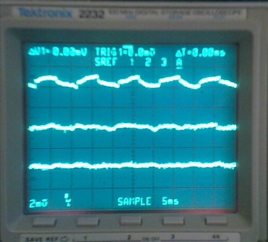
  • To further this discussion, below is a screen shot from my oscilloscope that illustrates this situation.

    I used the TPS7A4901 EVM.  The input voltage to the EVM is 6V.  I modified the EVM so that its output is +5.0V by changing R4 from 51.1K to 189K.  I then took the output and connected it as follows:

    EVM +output ------------+-----------+----------- Scope input

                           33K          |

                            |           |

                     2N7000 D           |

         Function gen ----G            Rpar

         F gen gnd --+      S           |

                     |      |           |

    EVM Ground ------+------+-----------+----------- Scope Ground

    So basically, I connected a 2N7000 NMOSFET so that it switched a 33K load on and off the regulator's output.  The function generator was set for 2Vpp, 100 Hz, square wave to turn the FET on and off.  The scope was set for 2mV/cm vertical, AC coupled, 20 MHz bandwidth limited, 5 mS/cm horizontal.  The probe was set for 1X, and I was careful to ground the exposed ring at the end of the probe to the EVM ground with a spring wire.  With a 5V supply this configuration switches about 150uA of load current on and off.  Then I added the parallel resistance Rpar.  On the attached scope photo, the upper trace is just the 33K load (150uA) switching on and off at 100 Hz with no other load.  The middle trace adds Rpar = 10K which adds a continuous current of 500uA.  This means that the overall current out of the regulator is now varying between about 500uA and 650uA.  The lower trace adds Rpar = 1K which adds a continuous current of 5mA.  This means that the overall current is varying between 5mA and 5.15mA.

    It can be seen that by my definition, the load regulation improves significantly as extra continuous current is drawn.  But this wastes valuable power in battery run systems.  I don't have a picture of it, but the lower trace is essentially the same as what the output looks like with the 33K and FET out of the circuit.

    .

    Note that this trick will probably not work with some other regulators like the TPS763XX for example.  Looking at figures 1, 2,and 3 in that part's datasheet, it is clear that there is what appears to be a perfectly linear relationship between load current and output voltage going all the way down to no load current.  Unfortunately this kind of Vout vs Iload curve is not shown on most LDO's datasheets.

    Does anyone know of a regulation scheme that will maintain 16 bit load regulation all the way down to no load?

    -Randy

  • Hi Randy,

    At extremely light loads, LDO's can experience the issues you have seen and your idea to simply add more leakage definitely improves the situation. The TPS7A49 is a 150mA LDO which seems to be quite a bit more than what you need. Also, since this is a battery powered application, you may want to think about the quiescent current consumption of the LDO itself. For light loads the Iq is nominally 80uA for the TPS7A49.


    For battery powered applications, we have the TPS715xx series (50mA) which only has an Iq of 3.2uA. Now this device does not have the noise performance of the TPS7A49. If you find it too high,  you can add filtering before and after the LDO to improve its noise performance. Also, depending on your application, you need to pay close attention to layout (long traces can exhibit antenna effects which are more pronounced with Low Iq LDO's). What I have seen done in the past is adding pie filters before and after the LDO to get the noise down to the desired level.


    I hope this helps.