Other Parts Discussed in Thread: TPS63710, LP5907, LP5912
Hi everyone,
Unfortunately, the issues are still here.
Part one of this mess is here
Even worse, i have improved the pcb a bit (at least i think i did) and tried the fixed version of the LDO TPS7A3725 (2.5V) without any luck.
At first everything worked for a few minutes and then trembling and random behaviour started.
I am at a dead end. Designing for months and i got stuck with an LDO instability issue. The last thing i would ever think...
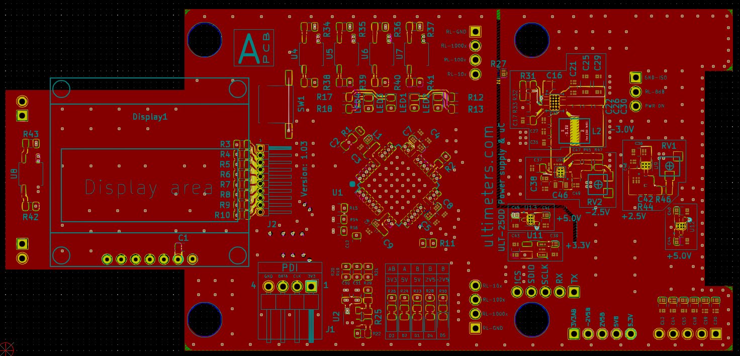
Here is the 6-layer pcb around the TPS7A37XX with the top layer solder paste areas visible
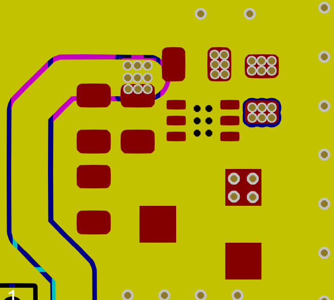
This ^ is the bottom layer. The ground plane is clearly visible.
This ^ is the inner layer 4. Just like bottom layer, the ground plane is the cyan colored area.

This ^ is the inner layer 3. There is no ground plane here. The blue area that you see (not close the edges) is the +5.3V rail that is supplying the TPS7A37XX.
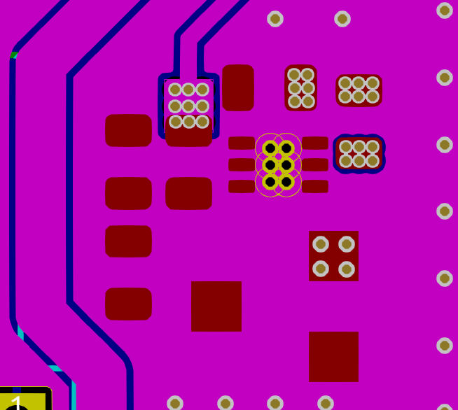
This ^ is the inner layer 2. Again, ground plane is dominant.
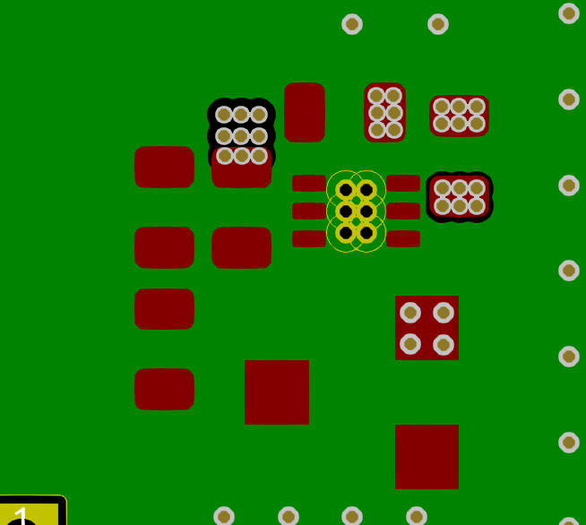
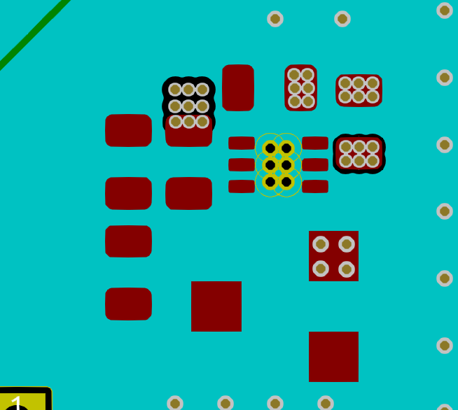
This ^ is the inner layer 1. Ground plane is under the feedback loop traces. The yellow trace going downwards is taking the output of the TPS to a pin header.
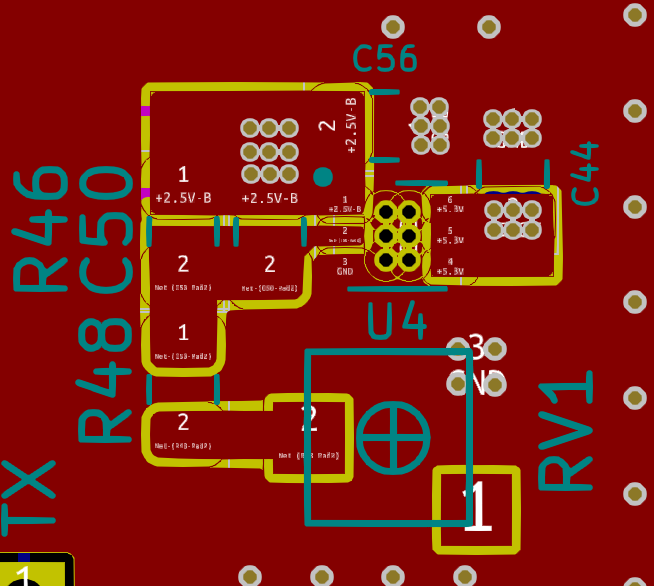
This ^ is the top layer.
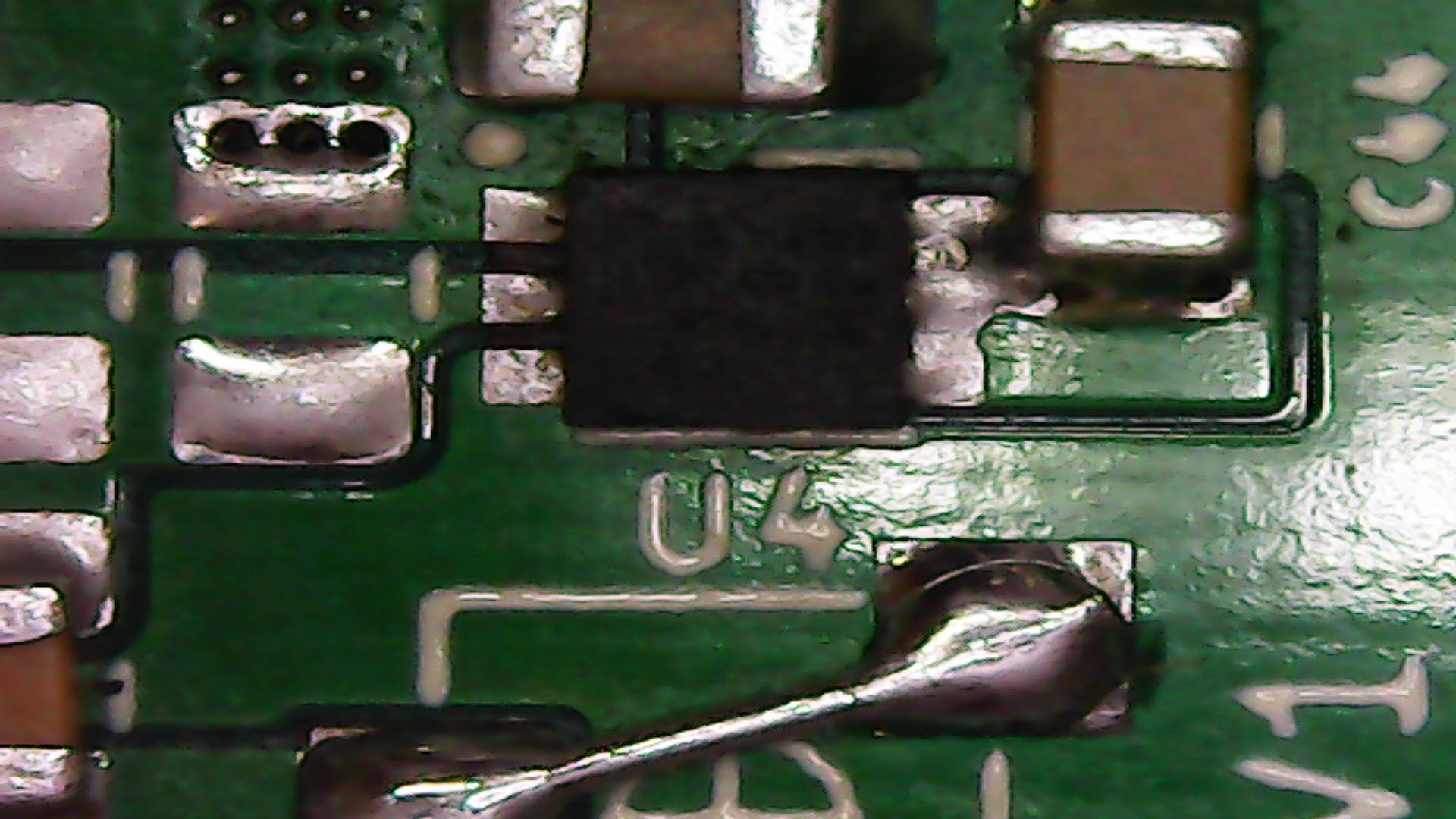
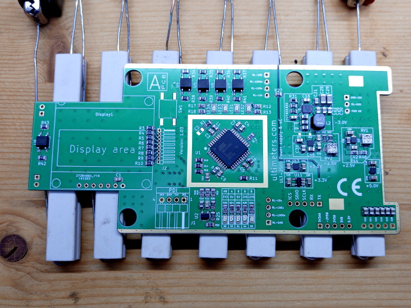
This ^ is the fixed version of the TPS soldered with the FB pin being decoupled by a MLCC 10nF as required by the DS in order to further reduce output noise.
What i find realy strange is that the 2x LP5912, 1x LP5907 and TPS63710 inverter smps are not facing any issues.
Could this be an inherent instability issue? I have already spent $200 for the first prototype pcbs and another $200 for the last set.
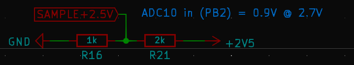
What about the critical selection of the MLCC caps?
DS says at p 8.1.1: "In applications where multiple low ESR capacitors are in parallel, ringing may occur when COUT× ESR< 50 nΩ-F.". Can you pls explain that?
I have selected this cap for both input and output: click here.
Have you got any suggestions? Should i be looking for a replacement?
Regards
Manos Tsachalidis