This thread has been locked.

If you have a related question, please click the "Ask a related question" button in the top right corner. The newly created question will be automatically linked to this question.

UCC256303: Current imbalance in the secondary windings of the LLC transformer

Part Number: UCC256303
Other Parts Discussed in Thread: UCC256403, , UCC27517A

Hi,

We are using this LLC controller IC for the 2.4 kW charger application (For output voltage 38V - 60V, Max load = 40A). We are facing the following issue:

During testing we found the current in both the secondary windings are not same (Current imbalance can be seen in both the windings), even though the gate pulses are present at both the MOSFETs.

The above mentioned phenomena doesn't occur always, as sometime we are able to load 20A-30A current with everything working normally (i.e. expected currents in both the windings). 

Please find the attached images of above conditions. The pink waveform is the the current through the center-tapped winding of the transformer and the yellow waveform is the voltage at the VCR pin. 

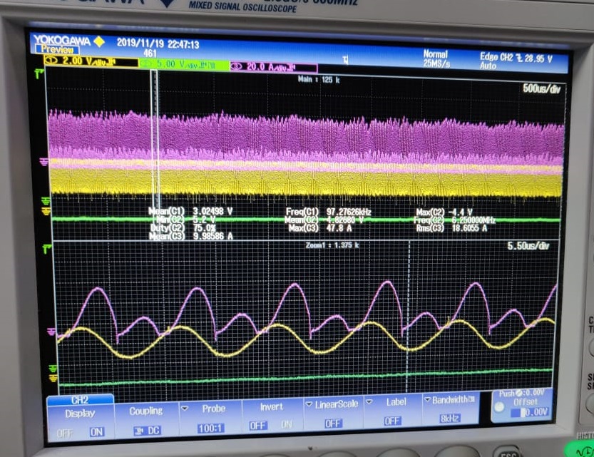
As it can be seen here the current is flowing more through one winding having very high value, with voltage at VCR pin. 

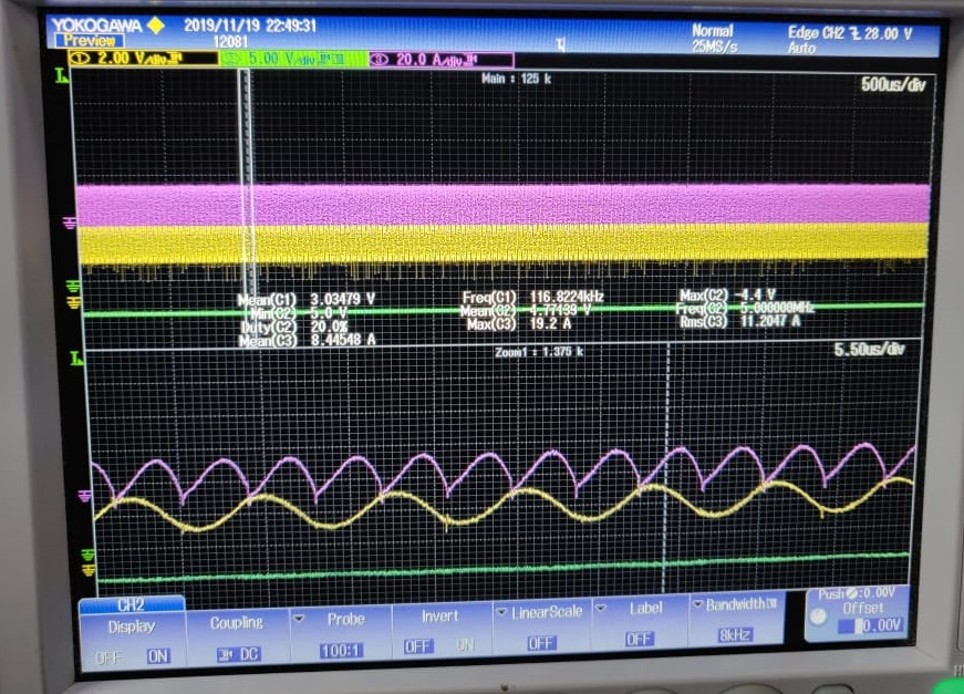
And as seen from above image current is balanced at lighter load.

Please suggest a solution to resolve the issue.

  • Shravan

    First off we recommend that you switch over to our latest LLC controller UCC256403.  This device is pin-to-pin compatable with the device you are currently using, but has improved features to enable it to get better performance.  Details are in this app note http://www.ti.com/lit/pdf/slua966.  We also have an excel calculator for UCC256403 that you can use to verify the entire power stage design http://www.ti.com/lit/zip/sluc675 

    For UCC256303, if you have not already we recommend you use our excel calculator to verify that there are no errors in the design http://www.ti.com/lit/zip/sluc634.  In order to help you we need the following information

    • Schematic of your design
    • Waveform of the switch node

    Please note that the gate driver for UCC256303 is only 0.6A/1.2A source/sink.  At 2.4kW this gate driver may be a little too small.  If you find that the FET is not turning on/off fast enough we recommend you use an external driver like UCC27517A to increase turn on/off strength.  You can use the internal level shift of UCC256303.

    Best Regards,

    Eric

  • Shravan

    It's been several days and we have not gotten the information needed to further assist.  I will close this thread.  Once you get the information please reply to this thread and the post will reopen for us to continue supporting.  If the thread is locked please post a new E2E thread and include a link to this post.

    Best Regards,

    Eric