This thread has been locked.

If you have a related question, please click the "Ask a related question" button in the top right corner. The newly created question will be automatically linked to this question.

LMZM23600EVM: Output oscillates under load when set to 12V output

Part Number: LMZM23600EVM
Other Parts Discussed in Thread: LMZM23600

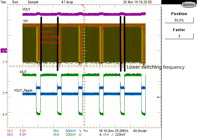
We're testing an LMZM23600EVM under ideal lab conditions. When the output is jumpered for 12VDC, the output oscillates wildly (5V excursions) with input-output differential voltages less than around 4V. With higher input-output differential voltages there is no oscillation. The load is an IP video camera consuming around 1.6W of power. The power source is a quiet lab supply. All cables are short and twisted. The's no oscillation  with a static resistive load or when jumpered for a 5V output.

  • Hi Sheldon,

    What is your input voltage from the lab supply? Can you provide a waveform of VIN,VOUT, and SW on the EVM? The SW node can be easily accessed through the exposed top side of the inductor on the power module. When probing SW, please make sure to not short SW to GND since this will damage and kill the part.

    The LMZM23600 should be able to provide 1.6W for 12VDC since it is rated up to a max output current of 500mA. 

    Regards,

    Jimmy

  • Here are two screenshots of the o-scope. The first one is the problem child, with a 1V input-output differential voltage. The SW Node is ringing . The second one is normal operation with a 5V input-output differential voltage. Changing from PFM to PWM had no effect nor did adding bulk capacitance to the output. I tried to add a feedforward cap across R2-R5 but the layout wasn't conducive to that so I put 20pF across R3-R5 and it had no discrenible effect.

    Thanks for the prompt reply Jimmy!

  • Hi Sheldon,

    From the first waveform, the SW node is in PFM so you will see several bursts followed by a decay after the output voltage has reached some percentage above the nominal output voltage and is to be expected of PFM condition. As for the input-output differential voltage, based on Figure 5 of the datasheet, the dropout voltage for a 12V output is roughly at the knee of 12.4V input for full load. This means the minimum differential input-output voltage is at least 400mV and should easily accommodate your 1V input-output differential voltage (ie. 13Vin / 12Vout). 

    What's surprising is the output voltage ripple even at PFM is around 3V which is very high and something I've never experienced on the EVM. You said there are no oscillation when using a resistive load. Can you confirm that this true for the same input/output condition in your first waveform? 

    Can you power the LMZM23600EVM up by itself stand-alone without the IP video camera and check VIN/VOUT/SW? If there is no issues with stand-alone operation, perhaps we need to look more into the input of the IP video camera to see how that is causing the output of the LMZM23600EVM to pull below 12VDC output. 

    Lastly, would you happen to have another LMZM23600EVM to recreate the issue? I want to rule out the idea that the EVM may be somehow damaged in any way which would impact operation. 

    Regards,

    Jimmy 

  • Hi Jimmy,

    I took more scope traces and added a clamp-on ammeter to display the camera's current waveform. There appears to be current flowing out of the camera at times. I don't have a schematic for the camera module, we didn't design this one. I'm trying to get more information. All traces were taken in PWM mode. Here's a table that explains the contents of the traces:

    Scope CNL

    Signal

    Name

    File Name Scope Trace #__

    1

    2

    3

    4

    5

    6

    7

    1

    VOUT

    5V

    5V

    12V

    12V

    12V

    OSC

    OSC

    2

    SW Node


    SYNC


    SYNC

    SUNC


    SYNC

    3

    VIN

    12V

    12V

    18V

    18V

    18V

    11.9V

    11.9V

    4

    Camera Current

    1mV=10mA

    SYNC


    SYNC


    SYNC


    NOTES


    1

    2

    2

    Note 1: Reduced input voltage to 11.9V while operating

    Note 2: Started up with input voltage of 11.9V

    Scope Trace #1


    Scope Trace #2


    Scope Trace #3


    Scope Trace #4


    Scope Trace #5


    Scope Trace #6


    Scope Trace #7

  • Hi Sheldon,

    Just to be clear on your application, you are trying to operate at 12V output given a close to 12V input. The downstream circuit is an IP camera that is expected to pull 1.6W of power. That would result in 1.6W/12V which would be roughly 133mA of current. 

    The issue you are seeing is in 'Scope Trace #6" where your output is oscillating with a peak to peak of roughly 4V based on CNL 1 (Yellow trace). 

    Focusing on "Scope Trace # 6) , from the looks of it, you are running a load transient based on  CNL 4 (Blue trace). However, it also looks like you are injecting current from the load into the LMZM23600EVM since the load current goes negative to CNL 4 reference (0V). One thing I would also check in that condition is the feedback voltage. If the feedback voltage is not 1V, the load may be unintentionally causing a dynamically controlled output voltage through current injection. You can access the feedback node by probing the point where the top(R2) and bottom(R1) feedback resistors connect. If this is the case, you can put a blocking diode in series with the output voltage and load such that reverse current doesn't go back into the EVM.

    Can you test the above?

    Regards,

    Jimmy

  • Hi Sheldon,

    Can I get an update on this? 

    On my end, I was able to get a LMZM23600EVM configured for 12V input and 12V output jumper selected. A voltage DMM is placed on VOUT which measured roughly 11.9V. The timescale was set to 10ms/div to try to match Scope Trace #6 timescale. A load transient of 0A to 500mA was performed on the EVM. Note that in both conditions between no load and maximum load, the device is still in dropout condition. The output voltage ripple was measured with an AC coupled probe measurement.

    When the load is high, the output voltage will slightly droop and the switching frequency is lowered since the device does not need to pulse multiple times to get to final value. When the load is low, the switch node needs to have more pulses to reach the desired output voltage so the switching frequency is increased. 

    In either case, the output voltage ripple (Channel 2 Blue) and output voltage (Channel 3 purple) is well regulated and reacts appropriately to the load transient. Even at max load transient between 0A to 500mA, the peak-to-peak output voltage ripple is no more than 250mV which is significantly lower than your measurements. 

    Regards,

    Jimmy