This thread has been locked.
If you have a related question, please click the "Ask a related question" button in the top right corner. The newly created question will be automatically linked to this question.
Dear support members,
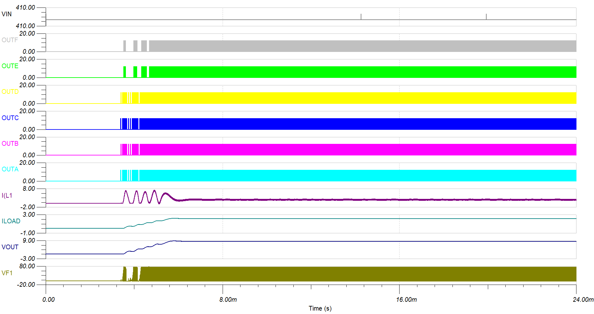
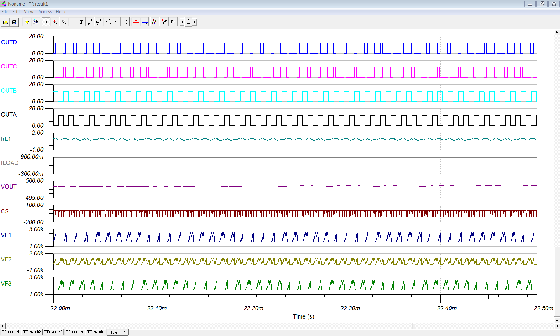
I am currently working on a design with UCC28950. I would like to have different voltage level at the output of the transformer. I had successfully get 30V at the Vout by using TINA as the simulation platform. However, when I was trying to generate 60V with the same method, it did not seems like working. After probing into the circuitry, I found out no matter how I change the ratio on the transformer, I will be getting the same output level from the transformer.
Could I get some advice on this?
Thanks.
Best Regards,
JC
Hello JC,
If you double the primary to secondary turns ratio of the transformer and change the output set point from 30V to 60V then you should expect to get the same secondary duty cycle.
Is this what happens when you make these two changes?
Do you have any waveforms or schematic available?
Regards
John
Hi John,
Good day to you. Thanks for looking into the issue I am facing and prompt reply.
I am currently modifying the transient model available in TI website. I am trying to modify it to 30V, 20A and 60V, 15A respectively. The modifications did are as below.
Transformer turn ratio, transformer LM, Lshin, Lout, Cout, R at current sensing transformer and also the R and C into EAN and COMP.
I had uploaded the schematics changes I did for 30V and 60V respectively in the link below.
In addition, below are the simulation results from the schematics uploaded.
Simulation for 30V :
Simulation for 60V :
You can observed that I put a probe at the transformer secondary winding (labeled VF1). Although I did change the transformer turn ratio according, but I am getting the same level of outputs for 30V and 60V. In addition, the Vout for 30V is as per expected, however, for 60V, the Vout only measured at 9V.
Looking forward for your advice.
Thanks.
Best Regards,
JC
Hi,
I already resolved this issue. However, when I am trying to step up the output voltage to 600V, the simulation is not working again.
The Output C and Output D is no longer 50% DC and the Vout I get is 500V.
In addition, the voltage of EAN also showing 2V instead of 2.5V as expected.
Do you have any idea why is it so? The simulation result is as attached.
Thanks.
Best Regards,
JC