This thread has been locked.

If you have a related question, please click the "Ask a related question" button in the top right corner. The newly created question will be automatically linked to this question.

BQ76940: Cell Balancing not working

Part Number: BQ76940

Good day,

I am working on a BMS for a 9S battery pack. I've got the other AFE features working, but it seems that the cell balancing is not working. Here is my schematic:

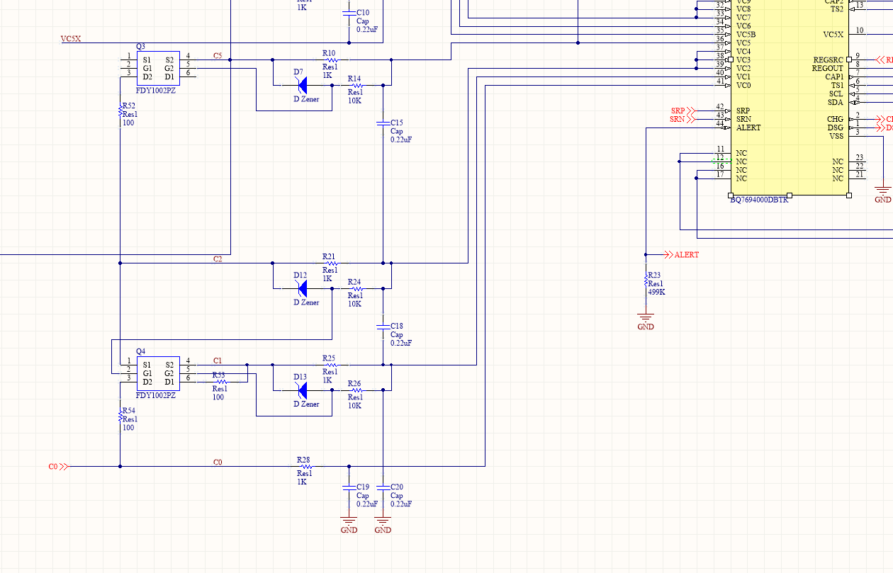
To test, I enabled cell balancing on cell 1, with the board being idle (not charging nor discharging). After 20 minutes, the voltage in cell 1 didn't change, which means that power wasn't dissipated through R54.

The values on this schematic are the values I used in my board, I've double checked this.

The external FETs seem to turn on, as I can measure a voltage across R54 using a multimeter whenever I turn on the cell balancing on cell 1. The voltage I should expect from R54 is the same as the cell voltage (which is 3.50), correct? But the problem is that that voltage that I get is fluctuating; here are the fluctuating values I get across R54 (cell 1 is 3.50V)

1.83 2.78 1.79 2.69 1.89 2.54 2.16 2.37 2.46 2.16 2.68
1.80 2.75 1.80 2.63 1.97 2.48 2.27 2.30 2.55 2.08 2.74
1.88 2.79 1.78 2.71 1.84 2.58 2.07 2.42 2.39 2.22 2.63

It seems that the values repeat every 11 ticks. Any suggestion I could do to resolve this issue?

  • Hi Robert,

    It sounds like the circuit is functioning since you can see the 3.5V across R54.  The cell balancing is duty cycled to allow balancing as well as measuring by the IC.  See figure 5 of the application note http://www.ti.com/lit/slua775 for an example waveform of the input pins.  The duty cycle is 70%.  Depending on how your meter reacts to the variation in the signal.  If you can set a longer sampling, averaging, or integration time you may get a more consistent reading.  Checking the voltages with an oscilloscope would be helpful for confirmation.  Since designers will often limit balancing current to keep dissipation in the battery low, using a thermometer or thermal camera can be helpful to determine if balancing is operating.

    For the amount of voltage change expected consider the passed change and the cell data sheet.  Neglecting FET resistances, at 3.5V and 100 ohms for R54, peak current would be 3.5/100 = 35 mA.  The control path in the BQ76940 would have about 3.5V/(2 x 1k) = 1.75 mA, so the total balance current would be 36.75 mA peak.  With the 70% duty cycle average balance current would be 36.75 x 0.7 = 25.725 mA.  Since you are balancing for 1/3 hour you will be pulling 25.725 x 1/3 = 8.575 mAh from the cell. If you have a 1 Ah cell this is < 1% of the capacity, so voltage may not change much, but it will depend on where you are operating on the voltage-capacity curve.  If your vendor does not provide a curve search for a typical curve for the type of cell you are using. Some cells will have the voltage rise quickly at full charge, some will rise more slowly.  If you are operating near mid-capacity point of a cell it may take a significant capacity change to see a voltage difference.  Your balancing current will be making a capacity adjustment, but it may not be apparent at that operating point.