Other Parts Discussed in Thread: BQ76200, , BQ769200
Hi everyone,
I am currently designing a battery pack with BQ76930 as the AFE and a BQ76200 to implement high-side switching of the protection CHG and DSCHG FETs.
A few specs of the pack:
- 7S LiIon
- Internal Balancing
- High-Side Protection FETs with BQ76200
- Controlled by external MCU via I2C
- 150Wh total Energy
- ~60A max Current
We want to measure the full current flowing out of the battery, including current for the MCU and all other peripherals (they need more current than the MCU). Also, to avoid problems in communication between the AFE BQ76930 and all our peripherals, it is desirable to share a common ground between them.
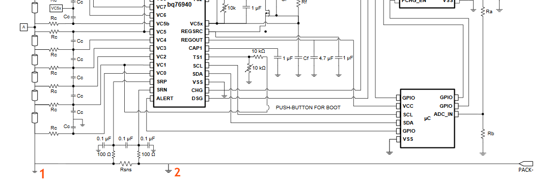
If we look at the typical application from the BQ769200, we see that the system is grounded between negative of the lowest cell and the current sense shunt (location marked with 1 in image below)
This means, that a) current for all devices sharing this groundis not measured by the shunt and b) there is a difference between the ground of the MCU is different from the ground of the AFE which will likely lead to communication problems? I see two options:
1. Ground all devices (including the AFE) at location 2: I have some doubt, because the datasheet states a) SRP-VSS as +-10mV, which could be achieved by switching SRP and ARN and b) VC0-VSS as 10mV as well. This can not be achieved any more, when the ground is placed after the current sense shunt.
2. Have two grounds, one for the AFE at location 1 and one for all other devices at location 2. Maximum Ground difference should be around 200mV which is way in the tolerances of communication limits?
What is your general recommendation?
Thanks,
Jakob