This thread has been locked.

If you have a related question, please click the "Ask a related question" button in the top right corner. The newly created question will be automatically linked to this question.

TPS548A20: TPS548A20 bode plot measure

Part Number: TPS548A20

Hi Admin,

I want to measure the bode plot of TPS548A20 so I will add a 10 ohm resistor in series Rm with the Rtop feedback resistor.

1. Generally the TPS548A20 have a VO pin connect to the Cout to sense the Vout, so I will change the VO connect to the Rm, then I can measure the bode plot. 

2. If I move the Rm far away from the controller area as the voltage sense to compensate the power plane. Whether the bode plot measurement still work? 

3. As some app note recommend use the AGND of the controller as the GND of AP300 instrument, will i use the local GND as the AP300 instrument? 

  • the 10 ohm resistor mark as Rm,

    We general add a 0ohm resistor in series with the boost Cap, can i use 0402 for both Boost R and C? 

    for the Cap to VREG and VDD, can i use 1uF X5R not the X7R? 

  • Yingchun,

    1. Yes the Rm resistor should be ahead of both the top FB resistor and the VO connection.

    2.  I always keep the RM resistor near the FB resistor near the IC.  The FB sense line does not carry any significant current.  It can connect at the furthest output capacitor to account for drops.

    3.  AGN should be sited as it is the ground termination for the FB resistors.  AGND should connect to PGND at a single point.

    4. 0402 should be ok to use, if you can find the proper rating.

    5. You can use X5R if you plan only operation up to 85 C.  Otherwise use X7R for 125 C. operation.

  • Hi John,

    Thanks for your quickly feedback. 

    That's means if I put Rm close to the furthest capacitor, i use the Rm to measure the bode plot. The VO pin connect to the Rtop which is close to the controller

       1. The Rm still can compensate the voltage drop for the power plane?

       2. The VO still can get the correct voltage sense?

       3. The measurement of Rm's bode plot still good? 

    What about the 1 ohm resistor in series with trace to VDD pin? Can i use 0402 as i saw it is 0603 on EVM

    thanks. 

    YC

  • YC,

    RM does not really compensate for anything.  It is just there to allow your network analyzer to inject the oscillator signal.  It is usually only 10 or 50 ohm, depending on your analyzer, so it is very small compared to your FB divider and has a negligible effect on the VO signal.  You can use 0402 if you like.  We use a lot of 0603 because they are easier to work with if you want to make modifications to the EVM.

  • Hi John,

    Thanks for your reply. 

    I saw the EVM show the AGND and PGND, can i just use 1 GND only? Will it effect the performance? Thanks.

    Regards,

    YC

  • YC,

    You should use a separate AGND and PGND.  They can be tied together to make a single ground.  Be sure to connect them at a single point only to prevent circulating currents.

  • Hi John,

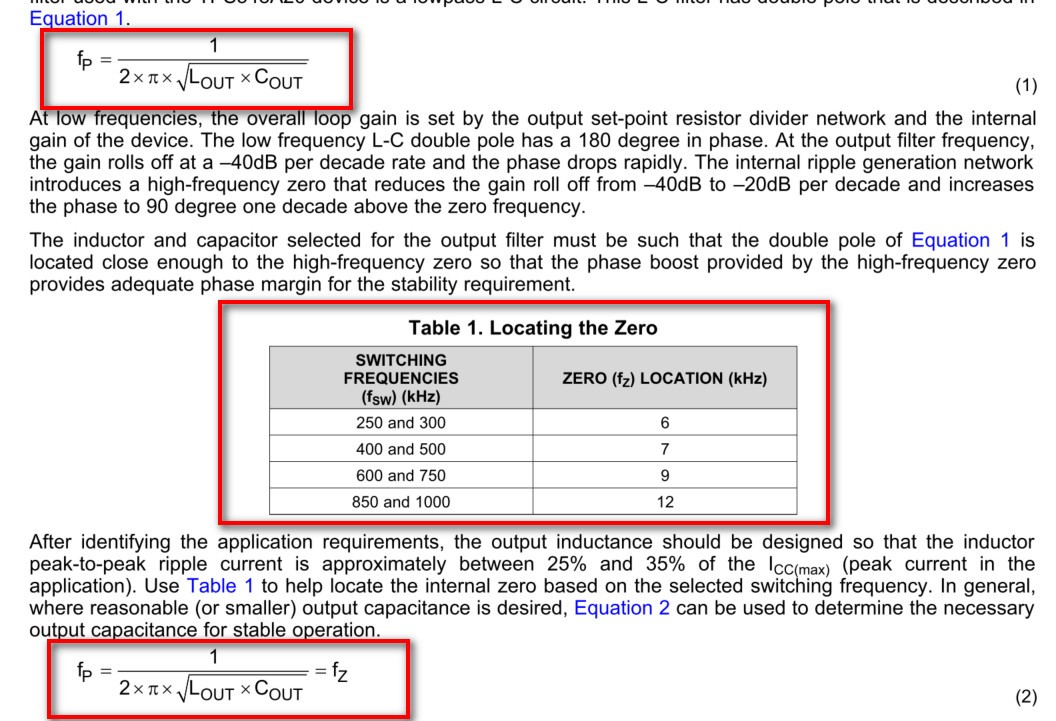
    Could you pls help to address the LC setting for the stability requirement on Datasheet. 

    on datasheet page 17, fp double pole should be close to fz like Table 1 shows. 

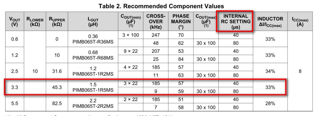
    1. What's the derating factor for all MLCC part? Why the Table 2 Recommended component value have a Cout range from min to max? 

    2. What's means of the INTERNAL RC SETTING? 

    If i have the 12Vin 3.3Vout, 8A, 

    1.5uH Lout, what's the recommended Cout for this design? Which setting of LC can meet the stability requirement? 

    table shows 3x100uF as the maxim, it that means I can't stuff more capacitance than 300uF if use all MLCC part?

    What about if i use PolmerCap mix with MLCC? tHANKS.

    regards,

    YC

  • YC,

    I think those questions are all answered in the paragraph text.  You need to derate MLCC for voltage bias.  You can generally get the exact amount from the manufacturer datasheets.

    The internal RC generates a ramp that is injected internally at VFB to reduce jitter and aid with stability.

    The rabge of output capacitors is pretty wide.  At the low end, you can use as little as 3 X 22 uF and as high as 20 x 100 uF.  lower total capacitance uses the short time constant, while higher amounts use the long time constant.  For an 8 A design, I think something in the 200 uF range would be appropriate.  It depends on your transient requirements.

  • Hi John,

    Thanks for your detail feedback. 

    I have a question on the VO sense. Generally the VO connect to B for voltage sense, we will change it to A for bode plot measurement. Can i leave the VO connect to A for mass production? So the VO may not sense the voltage on Cout. Will it affect the sense accuracy of the controller? Thanks.

    Regards,

    YC

  • YG,

    Yes you can leave it atA.  Use 0 hm resistor for Rm in production.