This thread has been locked.

If you have a related question, please click the "Ask a related question" button in the top right corner. The newly created question will be automatically linked to this question.

TPS92691-Q1: TPS92961:The switch frequency setting was not successful

Part Number: TPS92691-Q1
Other Parts Discussed in Thread: TPS92691, TPS92692

Hi team:

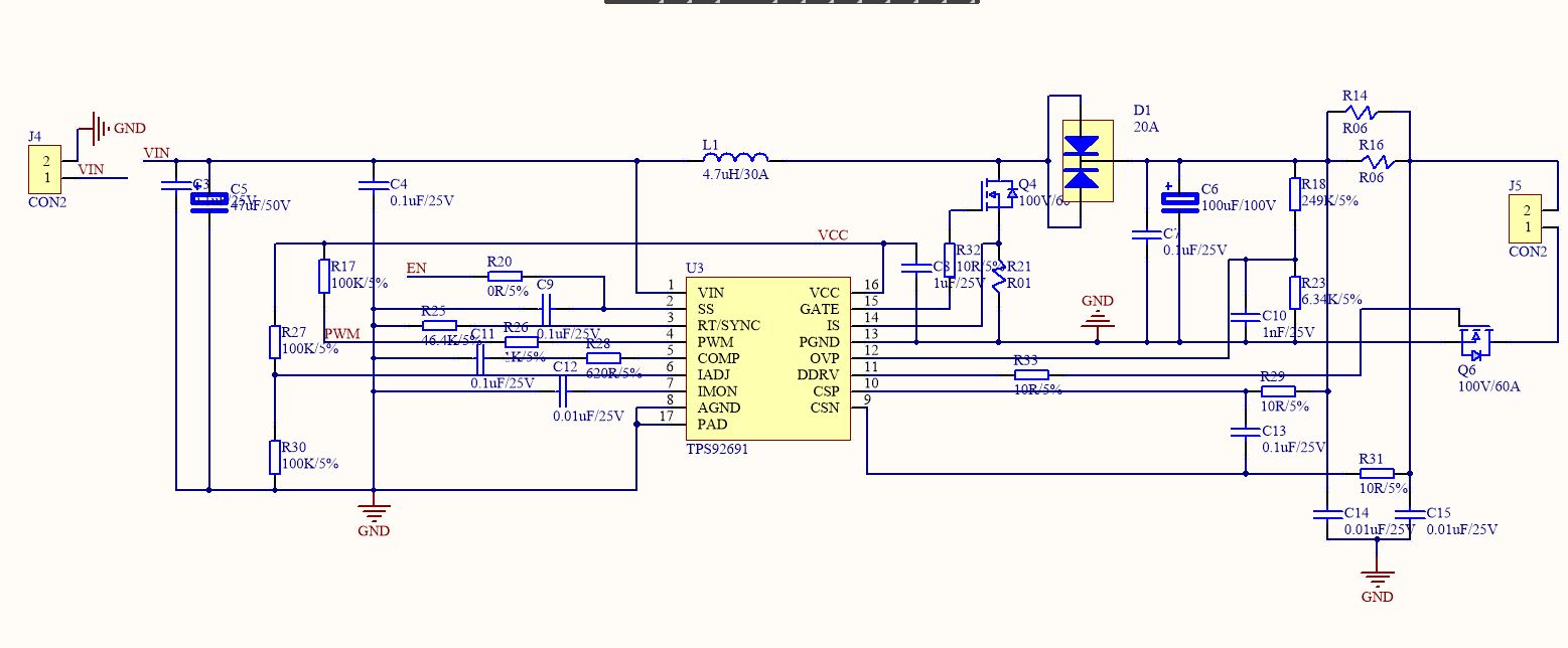
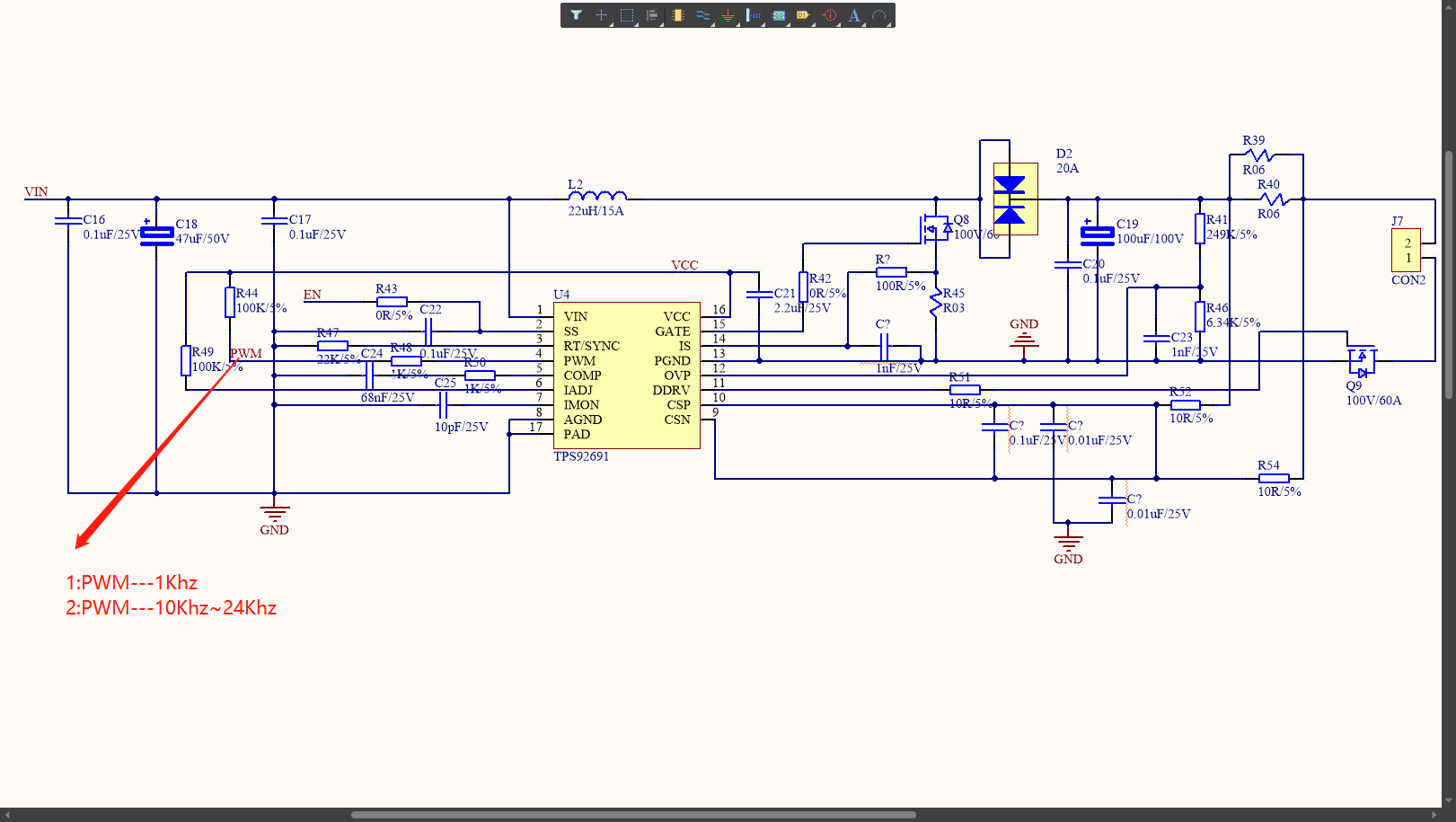
   I used TPS92691Q1 design a boost LED diver.There are several problems bothering me.

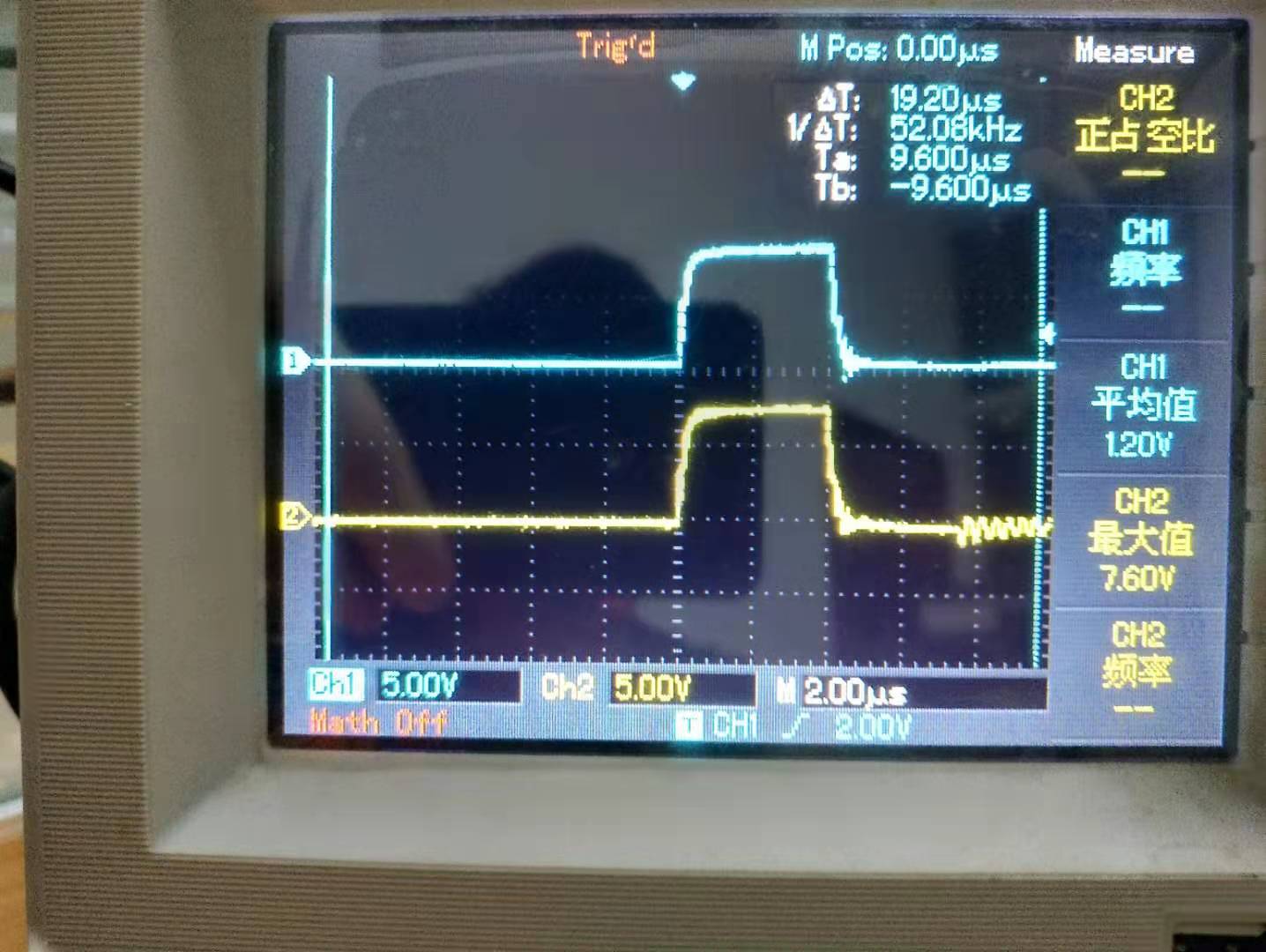
1:The dimming drive (DDRV port)waveform is always the same as the switching drive(GATE port) waveform;

2:PWM frequency <20Khz;

3:When I don't use RT(Generating switching frequency), the LED light still lights up at PWM frequency;

4:The efficiency is extremely low, and the d-pole of the switching MOS rings when it is turned off;

5:I used the BOOST circuit to follow the product manual, where the parameters were calculated according to the formula given and compared multiple times;

Finally, I feel that the failure to set the switch frequency led to a series of problems, but I have repeatedly checked the welding of RT and found no problems, so I came to consult the authorities.

CH1:DDRV

CH2:GATE

  • Hello,

    Can we have your input and output requirement for the design along with the LED output voltage?  We will also need your schematic to help understand your issue.  One question I have is why are you switching at such low frequency (20KHz)

    Thanks Tuan

  • Hello,

    We have not heard back from you so we believe you may have solved the issue.  The thread will close now but will reopen if you reply .

    Thanks Tuan

  • VIN:12-19V

    VOUT:24-27V(COB-VF)

    Iled:6.2A

    20KHZ  is not switch frequency,it is PWM frequency.I used the BOOST circuit to follow the datasheet.

  • Hello,

    We still need your schematic and part list to check the design.  The 20KHz dimming frequency can be high but it depends also on the duty cycle you are trying to achieve.

    Thanks Tuan

  • When I set the PWM frequency below 1KHZ, the switching frequency is the same as the dimming frequency, and the light is not on.When adjusted to 10KHZ above, the two frequencies are still synchronized, but the light is on, but its efficiency is very low, duty ratio more than 10% to protect, and ringing phenomenon is serious.

    I'm wondering if it has anything to do with the device, and I've seen people on the Internet buy a batch of devices, some are normal, some are the same as me, the two frequencies are always in sync,

    At the same time, thank you for your reply. I hope this problem can be solved.thank you.

  • Hello,

    It might be that you do not have the RC filter on the IS feedback that is causing you the issue.  Please refer to figure 32 of the data sheet for the Boost regulator.  The filter is R7 (100 Ohm) and C19 (1000pF).  This filter is to prevent glitches of switching edges from getting a faults trigger on IS input.  There are other issue with your design...C14 and C15 should be from CSP to ground and CSN to ground.  C8 for VCC decoupling should be a 2.2uF to 4.7uF. 

    The reason that the Drain of your switching FET rings is the fact that the current in the inductor has reached zero and this is normal with switching regulator. 

    Please use the spread sheet we have on the Boost calculator along with our reference design to help you with design and layout in the following link: 

    www.ti.com/.../toolssoftware

    Thanks Tuan

  • First of all, thank you again for your reply. Today I made the modification as shown in the figure above according to your suggestion.

    1:After adjusting the hardware parameters as shown in the figure, I set the PWM frequency to 1KHZ.The switching waveform is consistent with that of the datasheet.But after a certain value is reached, the COB automatically shuts down.As the duty cycle increases the noise of the inductor increases.

    2:Then I adjusted the PWM frequency to 10KHZ and above, and the PWM frequency and switching frequency waveform were synchronized, but the COB was normally lit.

    By the way, the hardware parameters are calculated according to the table you said.

    How do I make it out of sync and run as designed?

  • Hello,

    Please look at the input voltage at Vin and see whether it's dropping below the 12V input that you are designing for.  You will need to trouble shoot your circuit to determine the issue here.  This is a high power design so the part has to be rated so the layout can also be an issue.  Please familiar yourself with the part with the data sheet to help you debug.

    As far as Dimming at higher frequencies...I would recommend dimming at lower frequency like 1KHz for now since the gate drive of the TPS92692 has to be able to turn on the Dimming FET.  You can determine that by looking at the gate of the FET.  You can also short out R51 to 0 Ohm to help with going to higher frequency but getting 20KHz will depend on the FET that you use and whether the gate charge on that is low enough for the TPS92691 to turn it on and off specially at narrow duty cycle.

    Again...you will need to understand more about regulators and the part in order to debug this.

    Thanks Tuan