This thread has been locked.

If you have a related question, please click the "Ask a related question" button in the top right corner. The newly created question will be automatically linked to this question.

BQ34Z100: Four BQ34Z100-Z1 gauges are in parallel. Problem with getting valid RC.

Part Number: BQ34Z100
Other Parts Discussed in Thread: BQSTUDIO, BQ34110,

Dear TI team and community!

I am involved in BMS design currently.
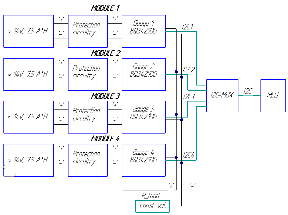
The problem I have encountered is: the design has four LiFePO4 modules* ( approx. 14V, 7.5 A*H, 30 A*H in sum) that connected in parallel.
Each module has BQ34Z100-Z1 gauge (to obtain state-of-health (SOH) from module; number of modules in design may change from 1 to 4 items) so, MCU collects data from four gauges.

During test charge-discharge cycles I have not got valid data about remaining capacity (RC), it didn't changed.
For example, I have discharged four modules in parallel for 2 hours with current in 4 A. The RC was still the same for every gauge - approx. 7.5 A*H.

Every BQ34Z100-Z1 gauge responds to commands via I2C and provide valid data for voltage, temperature and current.

  • Am I use correct approach?
  • Can I build such a system in principle: four modules with four gauges?
  • What can I try to do to fix the problem?

*Each module contains many 26650 batteries.

Thanks for any help!

Sincerely,
Andrei.

  • Hi, Andrei

        My understanding is that  you are having the bq34z100 in 4 battery pack and read data from these pack with a host MCU, these four packs are connected in parallel and connected to the same load.

        My questions are:

        1: How the I2C of these bq34z100 connected, are the data and clock signals simply ORed with same pull up resistor?

        2: How does the host MCU identify each battery pack?

        3: Is there any circuit to manage the load allocation for the 4 battery packs connected in parallel?

        4: Is there any protection circuit for each module? How the circuit manage the FETs if other packs outputs are higher than its self?

  • Hi, Steven.

    I have added diagram of the system. It contains 4 modules, that include 4 bq34z100 (1 gauge per module).

    1: Q: How the I2C of these bq34z100 connected, are the data and clock signals simply ORed with same pull up resistor?

    A: I2C pins (SDA, SCL) are connected to I2C-MUX via pull-up resistors.

    2: Q: How does the host MCU identify each battery pack?

    A: Host MCU switches between every battery via I2C-MUX. So, MCU communicates with bq34z100 in series. No address conflict.
    This approach was tested with another gauge and all was fine.

    3: Q: Is there any circuit to manage the load allocation for the 4 battery packs connected in parallel?
    A: As load I use resistor with constant value (couple of Ohms).

    4: Q: Is there any protection circuit for each module?
    A: Protection circuit helps against overcurrent, over- and udervoltage cases. When such event takes place, output from battery is cutted off.

    Q: How the circuit manage the FETs if other packs outputs are higher than its self?
    A: Unfortunately, I don't now much about protection circuitry. Before adding bq34z100 to module all batteries were connected
    to equalize them in voltage.
    Then was made couple of charge-discharge cycles.

  • Hi, Andrei

        Could the sense resistors for current measurement of bq34z100 are bypassed somehow? can you provide a log file with bqstudio when discharging for further inspection?

  • Hi, Steven

    1: Could the sense resistors for current measurement of bq34z100 are bypassed somehow?

    Current data from every bq34z100 seemed good. Sum of four current from four modules fitted well with Ohm law (load equals to 3 Ohms).
    Voltage data, temperature seemed also good.

    But with capacity I have a trouble.

    2: can you provide a log file with bqstudio when discharging for further inspection?

    I have attached charge / discharge log files.


    Also, I have an additional question.
    During tests with two paralleled modules that has BQ34110 device each (two BQ34110 in sum), RC values from every module were good.
    But with BQ34Z100 I have met the problem.

    Could it be related with different algos?

    "The key to the bq34z100-G1 device's high-accuracy gas gauging prediction is Texas Instrument's proprietary Impedance Track algorithm.", bq34z100 datasheet, p.10.
    "The bq34110 gas gauge uses Compensated End-of-Discharge Voltage (CEDV) technology to accurately predict the battery capacity and other operational characteristics of the battery.", bq34110 datasheet, p. 9.


    Does TI provide any reference design with couple of gas gauges in one schematic?
    Is it approved solution by TI experts?

    Can I use some ICs to prevent such a problem with RC in advance. For example, using OR-ings controllers (e.g. LM5050) or eFuse Power MUXes (e.g. TPS25944) to connect modules in parallell?

    Thanks much for your help!

    8054.bq34z100_data.zip

  • Hi, Andrei

        I checked your picture, but find the remaining capacity before discharge is 100%, and the remaining capacity after discharge is 0%, it actually changed. are you reading a correct register?

       Also, I noted that the RUP_DIS set after discharge, does your MCU send reset or IT enable command to the device during or at the end of discharge? or did you power cycles the bq34z100?

        bq34z100 and bq34110 are actually device working with different algorithms

        So far there is no such reference design for parallel gauge usage.

  • Hi, Steven

    For debugging, I have experimented with just one module standalone and made a couple charge-discharge cycles.
    Remaining capacity has no meaningful values. It really changed, not as increment value, but as boolean.
    Current, voltage and Q max passed Q in good agreement with test measurements.

    Concerning RUP_DIS. Yes, bq34z100 was power cycled. Module was in deep discharge state and protection circuitry cutted off the battery.
    Now I test module without power cycle.
    For data viewing and logging I use MSP430.

    I have attached pics below:
    - REGs before module charging.
    - charging process.
    - charging process.
    - REGs after charging.

  • Hi, Andrei

        The current is measured inversely on your target board, this messed up the gauge when you charge the battery, the gauge sees a minus sign for current value, it assumes the battery is being discharged, but you are actually charging the battery.

        Please check how SRP and SRN pin of bq34z100 are connected to the sense resistor, I believe they should be switched over with each other

  • Hi, Steven

    This is nice advice!
    The problem was really with SRP and SRN pins. I have switched over them and data from module look like truth now.
    I have attached pic, where single module charge process is shown.

    Also, I have tied two modules together and start to test. At first view, they work good, no problem as I met before.
    I plan to make additional tests and give feedback.

    Thanks much for help!

  • Hi, Andrei

        Thanks for the update!

        I think of one thing, since your configuration is 4 LiFe battery in parallel, you need to make sure the voltage is above Flash Update OK voltage when discharge the battery.

        The default value for this parameter is 2800mV which is appropriate.