This thread has been locked.

If you have a related question, please click the "Ask a related question" button in the top right corner. The newly created question will be automatically linked to this question.

TPS5430: TPS5430 wouldn't start

Part Number: TPS5430

Hi!

I have a weird behaviour of the schematic for 12-24 to5V buck regulator based on TPS5430.

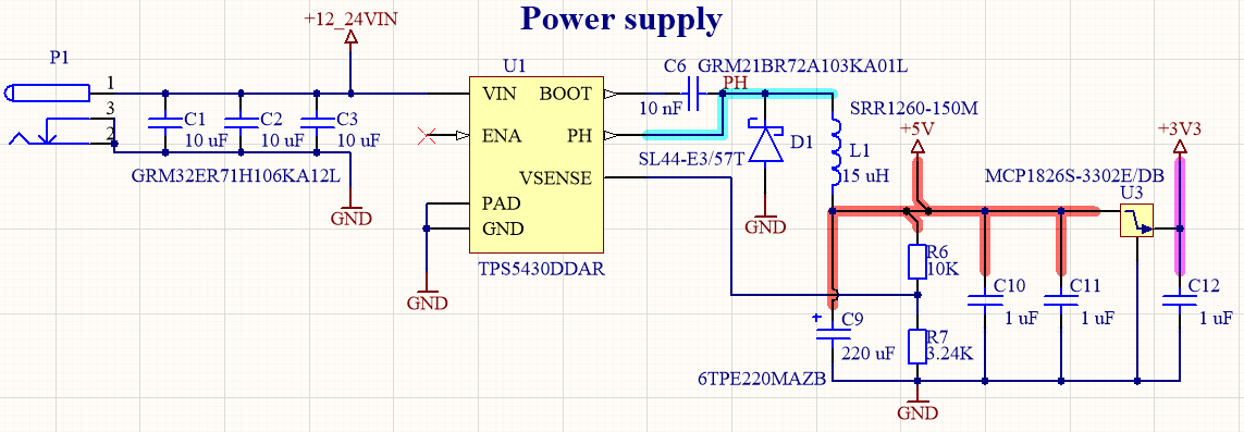
The schematic was desifgned in WEBENCH & the components were chosen according to the recommended BoM. I've cross-checked the WEBENCH calculations with the formulas from the datasheet and they seem to be correct.

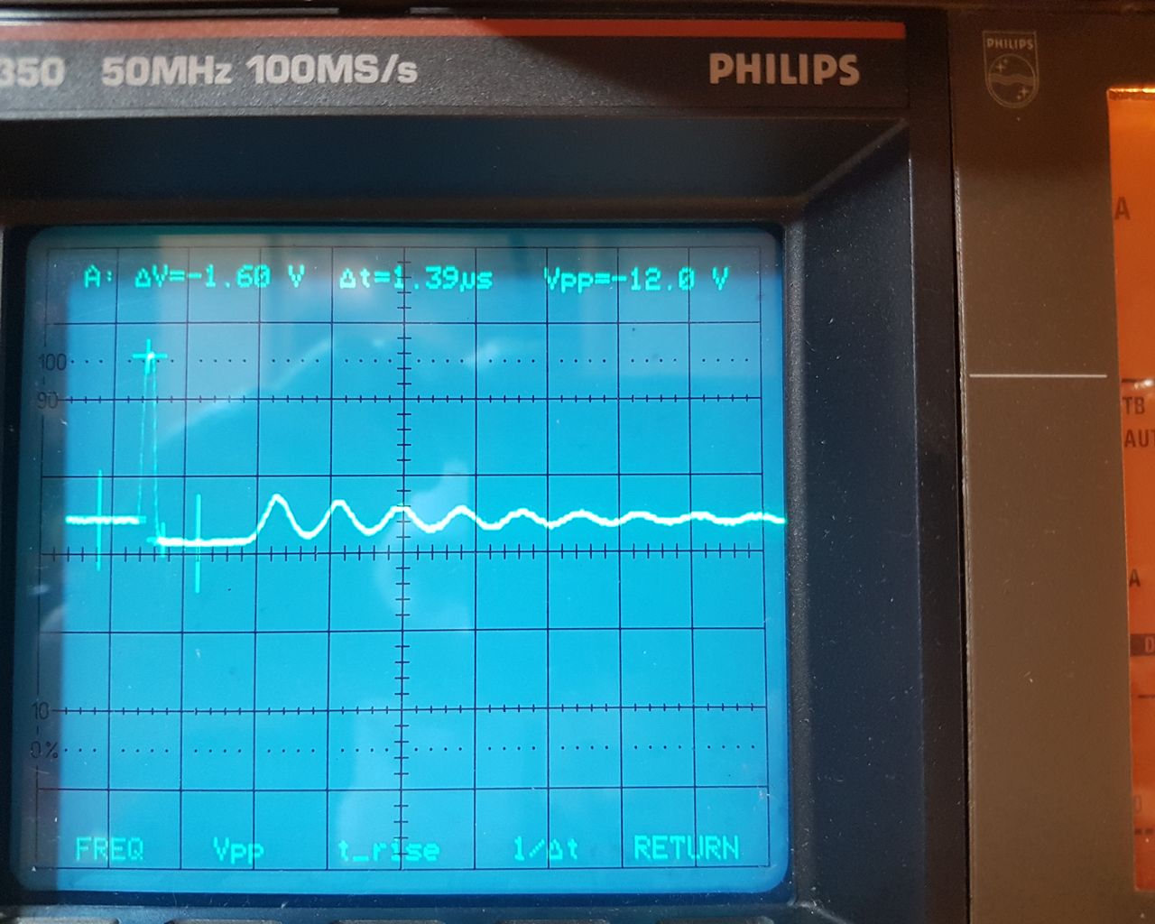
However, what I see is that the circuit wouldn't start. The PH pin oscillates and the output voltage is fixed to 1.225V. What is also weird, the Vsense voltage is the same 1.225V.

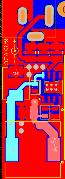
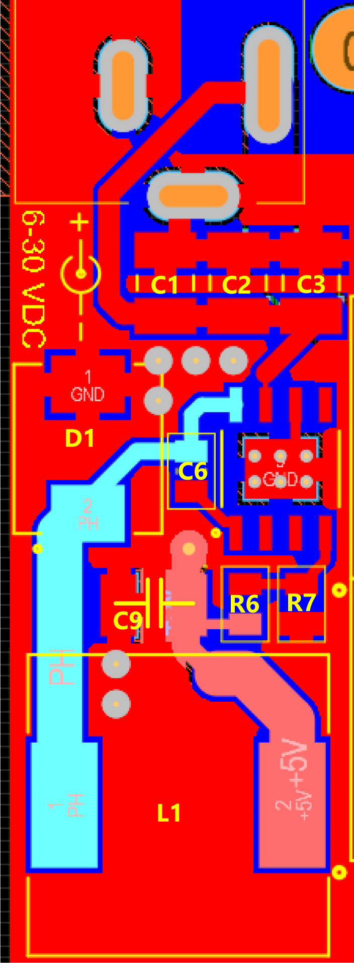
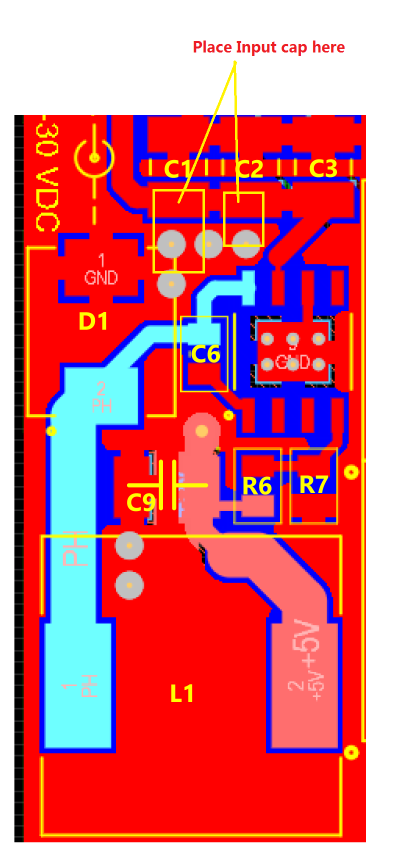
I've tried replacing the TPS5430 with another one - obviously no luck. I've also tried playing with input/output capacitance - no changes. I'm attaching the relevant parts of schematic & layout as well as an oscilloscope trace from PH pin.

Any advice/ideas?

  • Hi Zserg,

    The circuit BOM looks good, pls make sure you assemble devices with same parameter on your board.

    The PCB layout looks not good, where is the output caps? 

    There are 4 vias on right side of D1 GND, pls solder two 10uF input caps between the Vias and VIN trace.

  • Hi Andy!

    Thanks a lot for your reply.

    Sorry for confusion, I've attached the updated PCB layout with component designators displayed.

    The output cap is a single 220 uF solid electrolyte 6TPE220MAZB from Panasonic. It's C9 and it's located right above the inductor, so that the feedback resistors would be connected close to it.

    The input caps are three 10 uF MLCC from Murata GRM32 series (see the schematic in the first post for exact PN). This should give 18 uF total derated capacitance.

    All those parts were chosen from the list offered by WEBENCH designer (I still have my design it it, just cross-checked again), so I auume they should be OK.

    Would you recommend increasing input capacitance anyway?

  • Hi Zserg,

    Pls place Cin cap as below:

    1pcs 10uF 50V and 1pcs 0.1uF 100V