This thread has been locked.

If you have a related question, please click the "Ask a related question" button in the top right corner. The newly created question will be automatically linked to this question.

LM3409: Overshoot of light power measurement after load current transient

Part Number: LM3409

Hi team,

My customer is using our LM3409 for LED driver at their system.

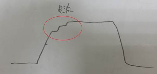
They have measured the light power and current waveform at load current transient as below figure.

They would like to improve the performance of overshoot behavior.

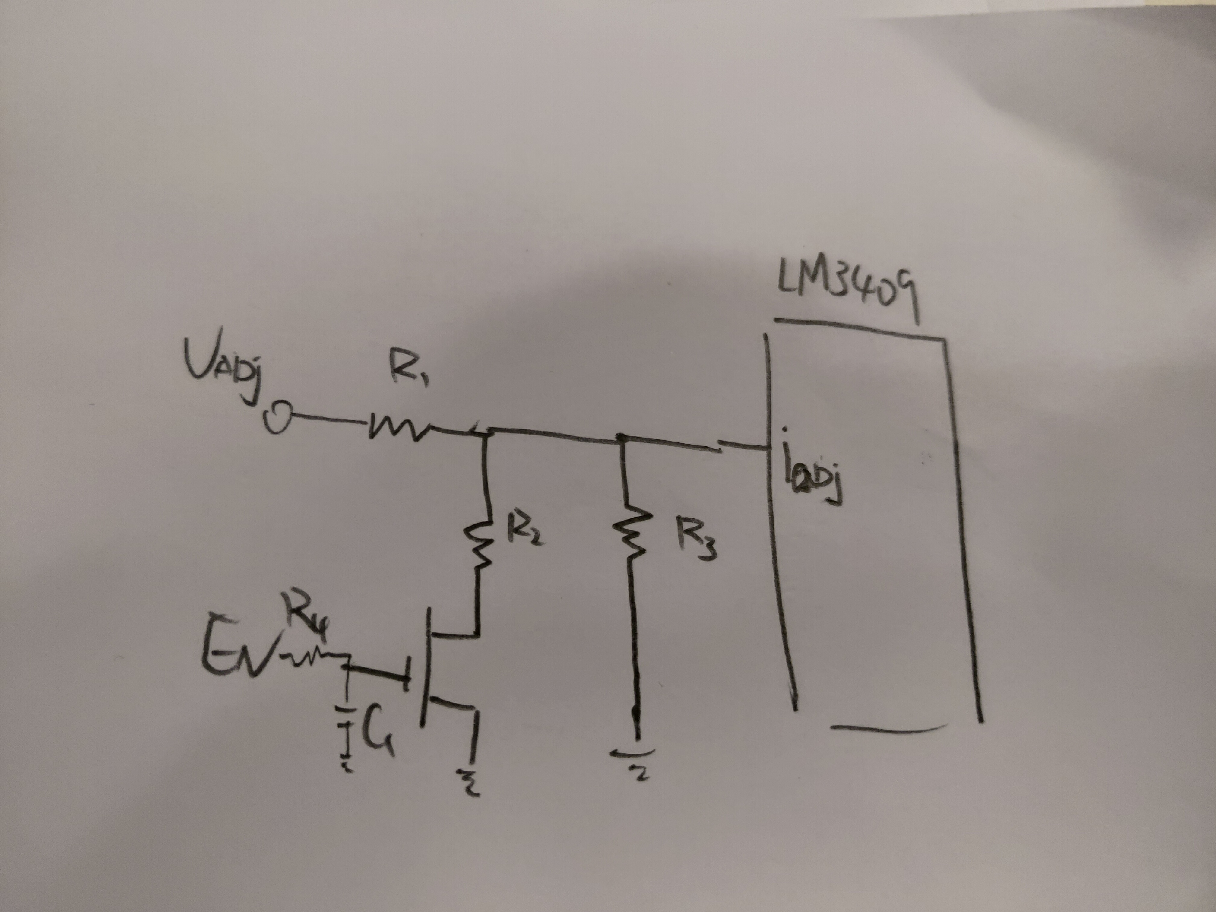
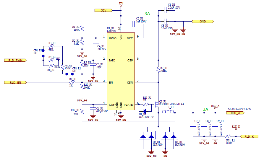
The schematic is as below. Could you kindly provide some suggestion? They also mention whether we can implement a step current load system to prevent the overshoot behavior as below figure. Could you guide us how to implement it in our system? Thanks. 

CH1: current, CH2: light power


Step Current waveform

  • Hello Feng,

    The LM3409 is a hysteretic controller.  It should not have overshoot.  Can they check the calibration of their current measurement?  How are they commanding the turn-on and off?

    The LM3409 regulates peak current with a controlled ripple based on the off-timer.  Current reaches a peak level, then shuts off while the inductor current ramps down.  The off-timer keeps the peak to peak ripple constant so, if operating correct and measured correct, there will not be overshoot.

    Where are they measuring the output current?  The LED string or the LED string and output capacitors?

    Best Regards,

  • Hi Irwin,

    Thank for your help. It is for DLP applicatio and LM3409 powered up for laser diode.

    Our LM3409 is giving the laser constant current but  the problem is the light power overshoot  behavior which is shown in scope waveform.

    The behavior is causing by the laser characteristics. Laser diode has a better light efficiency at the start-up.

    Laser manufacturing said that it will influence the life cycle of laser diode and customer also couldn't use a higher current load.

    Customer would like us to provide a way (like the step current ) to prevent these laser diode behavior.

    Now, I am thinking about using R4/C1 time constant to build up a two step iadj adjustment circuit as below figure.

    Do you think it is possible or any other suggestion for them? Thanks.

  • Hello Feng,

    Yes, there are a lot of methods to change the start-up behavior.  However before that Can they look at the inductor current.  Again, this is a peak current regulated LED driver, it should not overshoot.  If the current ripple is constant it should not overshoot.  Have they verified it is overshooting?

    Best Regards,

  • Hello,

    I'm going to close this since this has been taken up in another post.

    Best Regards,