This thread has been locked.

If you have a related question, please click the "Ask a related question" button in the top right corner. The newly created question will be automatically linked to this question.

TPS25927: Load Capacitance

Part Number: TPS25927
Other Parts Discussed in Thread: TPS25982

Hello Team,

Could you help with our customer's question:

The customer using TPS259271 for the current control on the output of the Power Supply 12 V, 2 A.

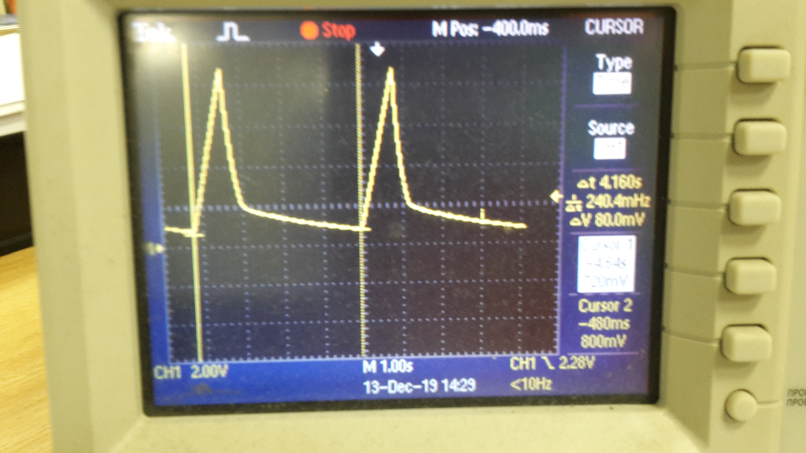
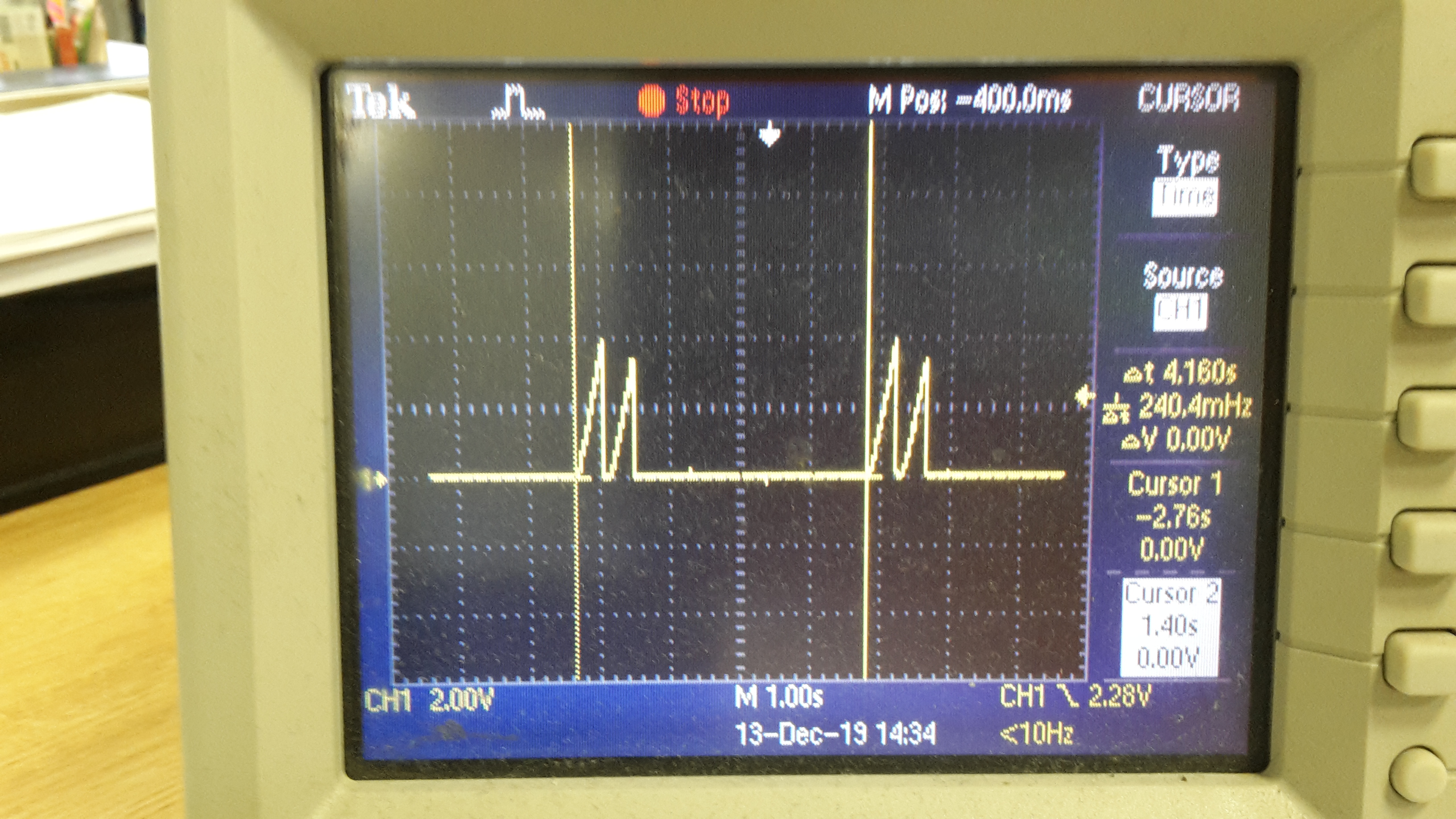
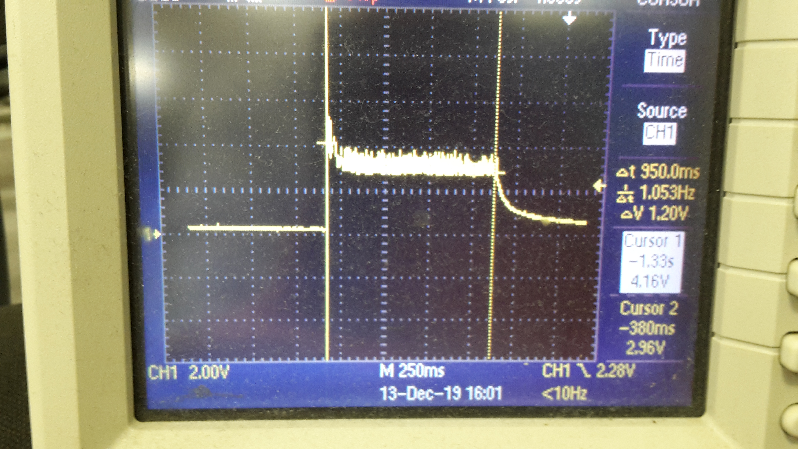
The problem - The power supply does not start (protection is triggered) with a large capacitive load (several security devices/sensors, expansion units connected).
While the current consumption of the system is 1 A when they start from another power supply.

The customer triyng to adjust passive components in TPS259271 scheme.

R ilim selected correctly on 2.2 A. Increasing its value does not help.
C, which on dVdT was increased from 1000 pF to 1 μF, also does not help.

DESIGN PARAMETERS:
Input voltage range, VIN               = 14 V
Undervoltage lockout set point, V(UV)  = 10,2 V
Load at start-up, RL(SU)               = 5 Ω
Current limit, IOL                     = 2.4 A
Maximum ambient temperature, TA        = 85°C

The question:
What is the maximum allowable Cout (Load capacitance)?
What should be the T dVdT value(Output Voltage Ramp Time) to achieve the maximum allowable Cout?

BR,
Ilya

  • Hi Ilya,

    Can you please input your system parameters in the design calculator http://www.ti.com/product/TPS25927/toolssoftware and send us for review.

    What is the max Cout you tried ? Can you share test waveform of Vin, Vout, input current during startup.

    BR, Rakesh

  • Hi Rakesh,

    System parameters attached.
    TPS2592xx-Design-Calculator-RevA_v2.xlsx

    The customer compared the calculated parameters with the values in the calculator and did not find differences.
    There are no problems with start when the capacitive load is low.
    When the number of blocks increases, problems with the start appear.

    The customer tried to test C dVdT value from 0 to 1000 nF.
    They expected that with an increase in C dVdT, the turn-on time will increase and at the same time the load with which everything will start will increase.
    But with C dVdT = 1000 nF and 100 nF TPS25927 does not turn on at all even without any external load.
    The output voltage rises to ~ 8 V within 1 second (with C dVdT = 100 nF) and then breaks down and after 4 seconds the cycle repeats.
    Why?

    If you connect an external resistive load of 2 A (7 Ohm - rheostat), then at the output the start cycle will break into 2 small pieces.
    Here, probably, the protection is already working, but it is also not clear.


    The limiting current is 2.4 A and they checked it, It really worked on a 2.43 A purely resistive load (rheostat).

    The last photo: output voltage at start (C dVdT = 1000 pF) with external load by real blocks when they have problem with start.
    Unit load current <1 A


    BR,
    Ilya

  • Hi Ilya,

    What is the total capacitance connected at the output rail of TPS25927 ?

    In the design calculator, you mentioned it is 1uF. Is it correct ? 

  • Hi Praveen,

    The customer tesed with Cout - 1uF and 470uF. No difference found.

    So the question is - What is the maximum capacitive load (several security devices/sensors, expansion units connected) TPS25927 can support correctly?
    How to achive it?(Configuration)

    BR,
    Ilya.

  • Hi Ilya,

    The maximum capacitive load that TPS25927 can drive depends on various parameters like the load during startup, ambient temperature, board Layout (RQJA) etc.. This is where the design calculator will help us to give an estimate on if the device will have a successful startup.

    • Cell D52 in design calculator will let you know if you will have a successful startup. 
    • Cell D51 gives an approximate maximum power dissipation acceptable for the given startup time. 
    • Cell D50 shows the amount of power dissipated in the internal FET of TPS25927 during startup (power dissipated in charging the output cap (D46) + power dissipated in providing load current(D49)).
    • You will have successful startup only when D51 > D50

    There shouldn't be any issue in driving a 470uF capacitive load with 100nF Cdvdt cap for TPS25927 if there is no load during startup. 

    From the waveforms you shared it looks like the device is hitting Thermal Shutdown threshold during startup and turning OFF. Looking at the Vout falling slew rate of the first waveform you shared, it seems that there is some load as long as the Vout is above 2V. 

    Can you share waveforms with Vin, Vout and Iin at above conditions ?

  • Hello Praven,

    Thank you for the recomendations! I asked the customer for the waveforms.

    Is it correct to use the TPS259271 as a current protection element in the output circuit of a 12VDC / 2.5A power supply? 2.5 A - is continious current.

    BR,
    Ilya

  • Hi Ilya,

    Yes, you can use TPS259271 for 12VDC, 2.5A continuous current application as an over current  and short circuit protection device.

  • Hi Ilya,

    Do you have any other questions ? if not, can we close this thread ?

  • Hello Praveen,

    Thank you for the reply!
    The customer made recommended changes.

    The best result they got after some tests - 1.5A (constant load after start) at room temperature.
    But they need 2.5A constant load up to 50C ambient temperature.

    So they reworked the design to work with 2.5A constant load.
    Could you check please their schematic? (How to send it privately?)

    Also they made waveforms you asked (Attached)

    BR,
    Ilya


    https://e2e.ti.com/cfs-file/__key/communityserver-discussions-components-files/196/pictures--tps25927.7z

  • Hi Ilya,

    It may not be possible to have a successful startup with Vin=14V, and with a load of 2.5A during startup at Ta = 50C. 

    You will have to consider a bigger eFuse like TPS25982 for this purpose.