This thread has been locked.

If you have a related question, please click the "Ask a related question" button in the top right corner. The newly created question will be automatically linked to this question.

LM5166: Swicthing Frequency with COT mode

Part Number: LM5166

Hi, 

Would you response below my question ?

[Back Ground]

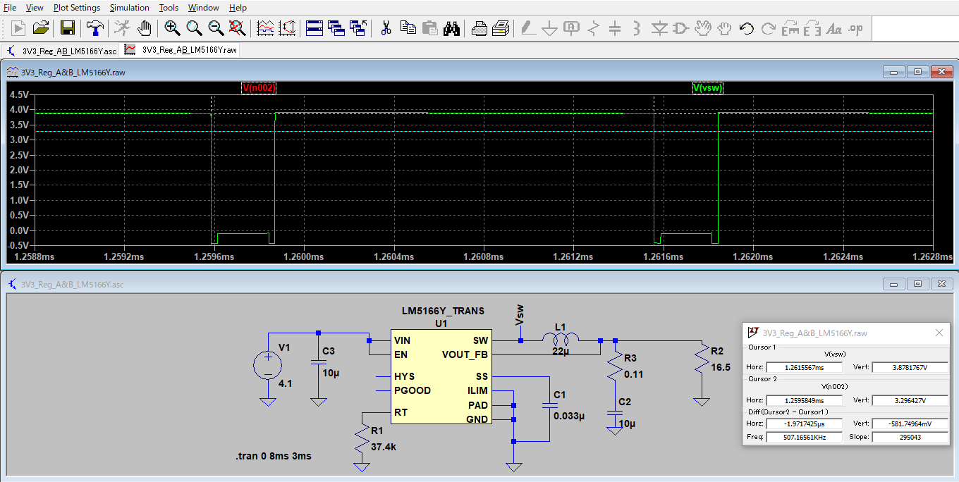
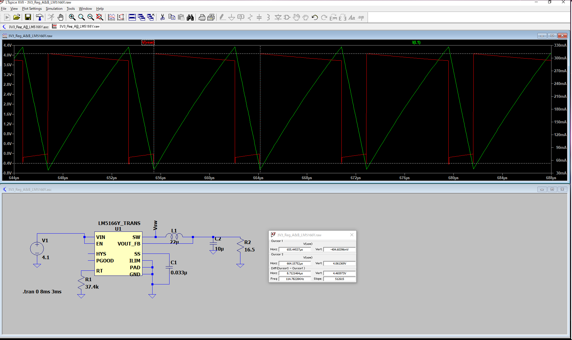
Currently, I am designing 3.3V non-isolated regulator with LM5166YDRCR(COT mode).

Then, I have simulated with LT spice to confrim swicthing behavior.(Spice Model "LM5166_TRANS.lib " that is provided TI web site was used.)

But , Observed switching frequency(SW pin) is 114.7KHz in spicte of Rt = 39.4kohm(According to foumula (4) in datasheet, It should be 478kHz ).

[Schematic]

Please see attached file.

[Question]

1) Why is swicthing frequecy 114.7 kHz, not 478 kHz ? 

2)  Would you provide foumula to calculate swicthing frequency under this condition ? 

It is urgently item for me. So, Would you please provide response as soon as possible ?

  • Additional infomation.

    I added 0.11 ohm (R3) between Vout and output capacitor in series.

    As the result, I observed that the LM5166Y operates switching frequency appx. 500kHz.( Nearly 478kHz)

    Would please let us know reason why result can be better by this R3 ? and why is R3 needed ?

  • Hi,

    Output voltage ripple is critical to feedback loop in COT mode, actual capacitor always has a ESR which brings a certain ripple. That's why you need to add the resistor. Thanks.

  • Thank you for your reply.

    Do you means that some ripple is needed for voltage feedback in lm5166 ?

    If yes, please reply below additional question ?

    1) How do I ensue that lm5166 operate stability by the ripple voltage . I found formula for ripple generation in table 2 in datasheet. Is design requirement for ensuring Lm5166Y operation of voltage feedback aspects ONLY meet these formula depend on filter type ?

    2) Why is ripple voltage needed for lm5166y ?  I would like to know its mechanism.

    3) If no ripple is present due to sufficient low ESR of output capacitance , in other words , Resr is not present , what is happened ?  

    4) I understand that ;

    Resr resistor must be inserted Individually ,  if esr of output capacitor is sufficient low.

    is this correct ?

    Thanks

  • Please see above my next questions.

  • Hi,

    My answers:

    1) Meeting Table 2 is a must for proper working.

    2) Because without a resistor, the inductor current always has a 90° phase shift with the capacitor voltage, the capacitor ripple voltage is used by feedback input so the feedback voltage must decrease monotonically in phase with the inductor current during the off-time. Hence we use a resistor (ESR of capacitor) to achieve this.

    3) Loop will be unstable.

    4) Yes.