This thread has been locked.

If you have a related question, please click the "Ask a related question" button in the top right corner. The newly created question will be automatically linked to this question.

BQ24070: bq24070 how to skip short circuit protection mode

Part Number: BQ24070

Hi,

I have trouble with the charger. I'm testing with the BQ24070

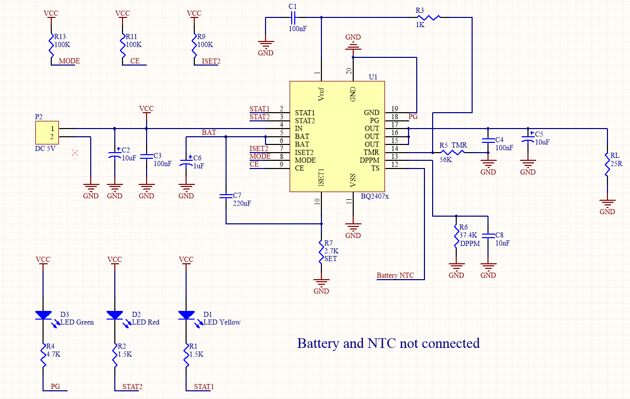
Schematic:

* I have 5V at the Input

* 25 ohm resistor Load at the output.

* No battery Connected.

Problem:

When I power the BQ24070, led PG is on and other are off. At the output it should be 4.4V, but instead there is just 0.25V

So my conclusion is that the device is on Short-Circuit protection mode.

I add a 10nF capacitor to DPPM pin, but the problem still there (when i add battery to circuit, it's work fine but not work when battery is not connected.

How can I skip from short circuit protection, when i have not battery in circuit and i can not disconnect the load from circuit.

thanks for your reply.

  • Hi Hop,

    I am attempting to recreate your problem  but am not seeing the 0.25V at output with a 25-Ohm load. Can you provide a full schematic of the circuit? It potentially is the short circuit protection but would like to make sure.

  • Hi Anthony,

    Thanks for your reply.

    I have a battery pack that contain battery and NTC together and In this test we have not battery pack in circuit.

  • Hi Hop,

    Alright, everything looks fine.

    The short is declared since the output doesn't go above 1V on power-on. You can use a 500-Ohm resistor as a pullup from IN to OUT to pull the output higher than 1V. You can find more details in 8.3.5 of the datasheet (Short-Circuit Recovery). 

    Let me know if this helps.

  • Hi Anthony,

    Datasheet note:

    "Short-Circuit Recovery

    The output can experience two types of short-circuit protection, one associated with the input and one with the
    battery.
    If the output drops below ~1 V, an input short-circuit condition is declared and the input FET, Q1 is turned off. To
    recover from this state, a 500-Ohm pullup resistor from the input is applied (switched) to the output. To recover, the
    load on the output has to be reduced {Rload > 1 V × 500 ohm/ (Vin–Vout)} such that the pullup resistor is able to
    lift the output voltage above 1 V, for the input FET to be turned back on.
    If the output drops 200 mV below the battery voltage, the battery FET, Q2 is considered in short circuit and the
    battery FET turns off. To recover from this state, there is a 10-mA current source from the battery to the output.
    Once the output load is reduced, such that the 10-mA current source can pick up the output within 200 mV of
    the battery, the FET turns back on.
    If the short is removed, and the minimum system load is still too large [R<(VBat-200 mV) / 10 mA], the
    short-circuit protection can be temporarily defeated. The battery short-circuit protection can be disabled
    (recommended only for a short time) if the voltage on the DPPM pin is less than 1 V. Pulsing this pin below 1 V,
    for a few microseconds, should be enough to recover.
    This short-circuit disable feature was implemented mainly for power up when inserting a battery. Because the
    BAT input voltage rises much faster than the OUT voltage (Vout<Vbat-200 mV), with most any capacitive load
    on the output, the part can get stuck in short-circuit mode. Placing a capacitor between the DPPM pin and
    ground slows the VDPPM rise time, during power up, and delays the short-circuit protection. Too large a
    capacitance on this pin (too much of a delay) could allow too-high currents if the output was shorted to ground.
    The recommended capacitance is 1 nF to 10 nF. The VDPPM rise time is a function of the 100-mA DPPM current
    source, the DPPM resistor, and the capacitor added."

    So:

    500-Ohm pullup resistor is enable internally and if want to add another resistor, most use a 133-Ohm resistor to pullup output voltage to 1V in 25-Ohm load. but, this is not good solution for variable load.

    Regards,

    Hop Hoh

  • Hi Hop,

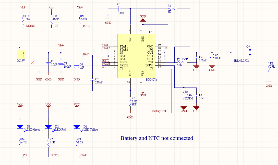
    At the moment, the suggestion is to use an NMOS in the hopes that it delays the short circuit detection on boot up. Connecting the OUT to the GATE and DRAIN while the SOURCE is connected to your load. The hopes is that the delay of the NMOS connecting drain and source will be enough for the short circuit detection to pass. Would this possibly work for your solution with a variable load?

  • Hi Anthony,

    I'll give it a test and inform you of the result.

    Regards,

    Hop Hoh

  • Hi Hop,

    Just wondering if you had any updates from testing.

  • Hi Hop,

    I haven't heard back in a while. Marking this as resolved but should that not be the case, feel free to reply back.

  • Hi Anthony,

    I test it and it work, but this is not the best solution.

    I test the circuit with IRLML2502 and AO3400A. they need at less 1V on GS, so out put voltage drop to 3.4V while bq24070 out put voltage is 4.4V.

    So This did NOT resolve my issue.

    Regards,

    Hop Hoh

  • Hi Anthony,

    Thanks for your recommended circuit.

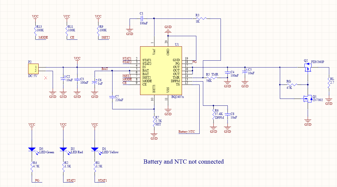
    I test bellow circuit and it work fine with 2.7 ohms load and got 4.2V on RL.

    So, This resolved my issue.

    Regards,

    Hop Hoh