This thread has been locked.

If you have a related question, please click the "Ask a related question" button in the top right corner. The newly created question will be automatically linked to this question.

UCC28070: The zero crossing flat area is too large

Part Number: UCC28070


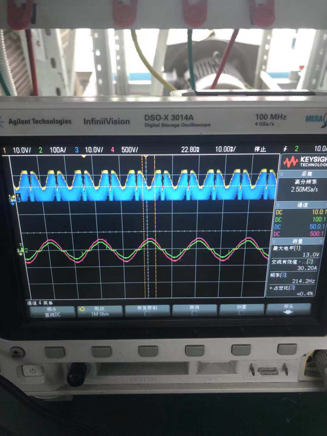
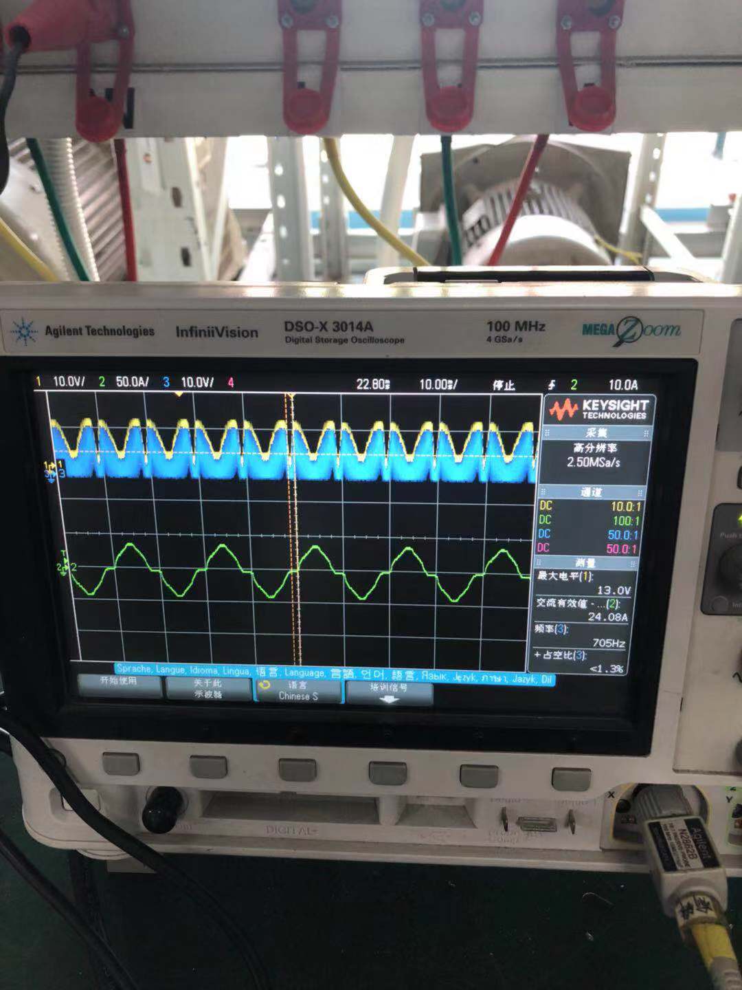
At present, I use your UCC28070 chip to make a 220VAC input, Uo = 390V, Po = 5000W PFC product, F = 65KHZ, Dmax = 0.97. The circuit refers to the TI 5KW circuit. The debugging waveforms are shown in following. At present, the half-load power factor is 0.95 and the 4KW load power factor is 0.985, which does not achieve the expected effect of 0.99 or higher. There are a few points of current questions that require consultation.    1. The current zero-crossing platform is too large (the green line is the grid input current waveform and the red line is the grid input voltage waveform). How to eliminate it, the current dead zone platform seriously affects the PF value increase.    2. How to design if the RIMO increases?    3. How to design Rsyn resistor is more reasonable.

  • Hello ,

    It is very difficult to understand your post.
    If these results refer to a TI reference can you please post the TI reference design number so that I can refer to the documentation ?

    Some other questions that needs to be answered:

    (1) The input current looks to be distorted. 
    This is more likely to be the cause of the lower power factor than the the dead zone around the zero crossings.
    The pfc can be designed for a full load power factor of 0.99 at low line but you will always get a lower power factor as the load decreases.
    You will not be able to get 0.99 power factor at half load.
    If this is a TI reference design you should check the test results and see what to expect.

    (2) Why do you want to change the value of the IMO resistor?
    This resistor needs to be calculated properly as described in the data sheet and applied in the Excel calculator.
    If you dont do this then you can expect poor circuit performance.

    (3) What do you mean about a reasonable Rsyn value?
    The Rsyn value is reasonable if it is correctly chosen.
    Otherwise you can expect poor circuit performance.

    Regards

    John


  • Wave distortion pictures, can they analyze them? What factors may be related for cross zero plat area?

    Any suggestion can we modify to get pure sine wave?

  • Now we  think current  cross zero area is large as picture, How can we improve it?

    Do you need us provide more design specs ?

    We refer TI PMP4311 5KW design.

  • I am closing this post since you have moved the discussion to email