Hello,
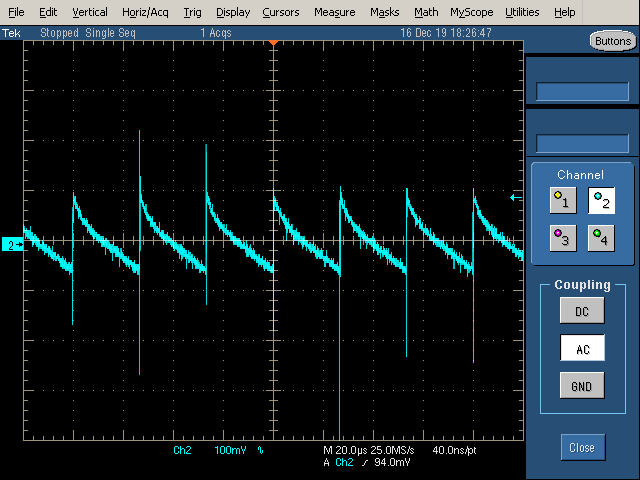
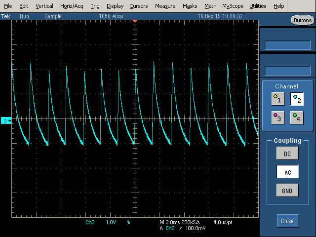
I have a TPS62173 that is being used to power only the digital interface section of two I2C devices. After the devices showed signs of constant POR conditions, I probed the 5V rail produced by the TPS62173 and noticed that it was a saw tooth like waveform.
I then removed the I2C devices the regulator was powering and took the following screenshots:
No load condition
250mA purely resistive load
Schematic clip of device
Suggestions on where to start? The layout if very tight with CIN and COUT very close to the device, SW node is short and wide, VIN and 5V are separate planes, and the board has sufficient ground planes. Nothing else is attached to the VIN rail on these test boards.
Thanks in advance


