Hi,
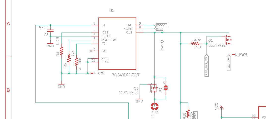
We've been using the BQ24090 for years in a few designs and it's been pretty solid, with thousands of units in the field. With a new design variant I'm seeing some weird behavior that I'm having trouble understanding.
The previous designs used a single 14500 cell, which is more frequently removed and charged in an external charger - the BQ24090 was mostly provided as a backup charging mechanism, so it's hard to say how prevalent this problem might have been in those versions. The version that's having trouble has five parallel 10440 cells and the BQ24090 is the only charging mechanism provided.
The issue is that when USB power is connected, the IC always shows !PG but might not show !CHG, even though it seems to be charging. It seems to be dependent on the system load. The main load is an LED array whose current draw varies (often quickly) over a wide range from maybe 20 mA to about 2000 mA. When !PG goes low, the system halts the LED display and shows a single charging status LED (yellow for charging, green for charged/powered), and the whole array can be switched off for faster charging. Only !CHG often doesn't become active, despite the battery being in the normal chargeable range and current draw indicating that it's charging.
The weird part is that the 'shutting down' signal for the LED array - a bright flash fading to black - will usually cause !CHG to respond. I think this has to be caused by either the current draw or the resulting voltage drop; I've ruled out a software problem by showing that it doesn't work if the master brightness of the array is turned down.
ISET is 680R, ISET2 is low, PRETERM is 10k, and TS is 10k. The base system load (mostly MCU and WiFi hardware) is 80-110 mA.
I've partly worked around it for now by adding a flash effect to signal when the USB cable has been connected. Obviously that's a kludge and not a good long-term solution, and it's not working completely. The system can go into its lowest power state, where the load (apart from the battery) is under 2 mA, and in the example on my workbench right now it's drawing 310 mA for charging. If I unplug the cable and plug it in again, it wakes up the MCU and does its "USB was connected" flash, but !CHG is high and no amount of flashing gets !CHG to go low again, until the USB cable is disconnected and reconnected.
Again I ruled out a software issue by restarting the system from its power button; this uses exactly the same wakeup path as when !PG is asserted, so it's not a problem in the MCU GPIO configuration or anything. Everything is the same except that the charger hasn't been disconnected.
The weird part is that charging seems to be proceeding normally. In the time I've had this test unit sitting on my bench, with the MCU in full shutdown, the current draw at the USB input has dropped to 260 mA and is still falling. I checked the !CHG pin state and it's at VCC, indicating the charger ought to be off, yet charging continues - it just dropped to 240 mA.
What gives? This is causing customers some major headaches, since they're left without a way to reliably tell when the device has finished charging. I can try to get some more measurements, but my easy-to-probe desktop development version of the board isn't set up for the 5x10440 battery configuration and until I get something wired up I'm limited to testing in the production version, which is very hard to work with because of its size and form factor. I wanted to check here first and make sure I'm not missing something obvious.
Thanks,
Scott


