This thread has been locked.

If you have a related question, please click the "Ask a related question" button in the top right corner. The newly created question will be automatically linked to this question.

TPS23880: TPS23880 Power Policing issue

Part Number: TPS23880

Hi, 

Customer's project requires class 8 power control of 75W. Customer sets the Power Policing register and it dose not work. The load power is greater than 75W, and PSE dose not cut off. It would cut off until 90W.

Could you give a guider or suggestion for power policing setting? Thanks a lot.

1. Customer's code:

            //CLASS8

            else if(CLASS_8_4P_SINGLE == s_classifStatus)

            {

                ret = tps_SetDeviceOperatingMode (addr1, OPERATING_MODE_SEMI_AUTO, OPERATING_MODE_SEMI_AUTO, OPERATING_MODE_OFF, OPERATING_MODE_OFF);

                ret = tps_SetDevice4PPowerAllocation(addr1, _4P_90W, _4P_90W);

                ret = tps_SetPortILIM(s_sysChanNum, _2X_ILIM_FOLDBACK_CURVE);

                ret = tps_SetPort4PPolicing(s_sysChanNum, 150);

                ret = tps_SetPortPower_4P(s_sysChanNum, TPS_ON);

            }

2. customer's design target:

Oliver Ou

  • Hi Oliver,

    The PCUT value will be set at turn on by PSE device based on assigned class level. Since your PD is class 8, PSE would set the PCUT to 90W based on IEEE standard. If you want to set the PCUT to a different value, you will need to adjust PCUT after power enable bit is set in 0x10. Thanks.

    Best regards,

    Penny

  • Hi Penny,

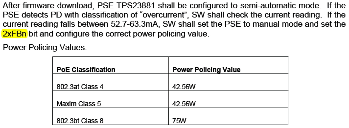
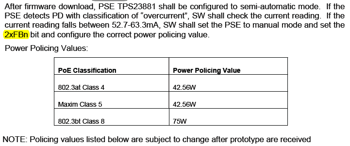
    Customer has tried the method you have provided, it can work for. The power policing is right for 803.3at class 4 and 802.3bt Class 8.

    But for Maxim Class 5 mode (which is listed  in above table), the output is normal, but power policing is not right, the port would not shut down correctly. Dose Maxim Class 5 mode needs a special configuration?

    Below is customer's configuration, the PD would not cut off even the power is higher than 50W. Could you give some suggestions?

    --------------

    Customer's configuration:

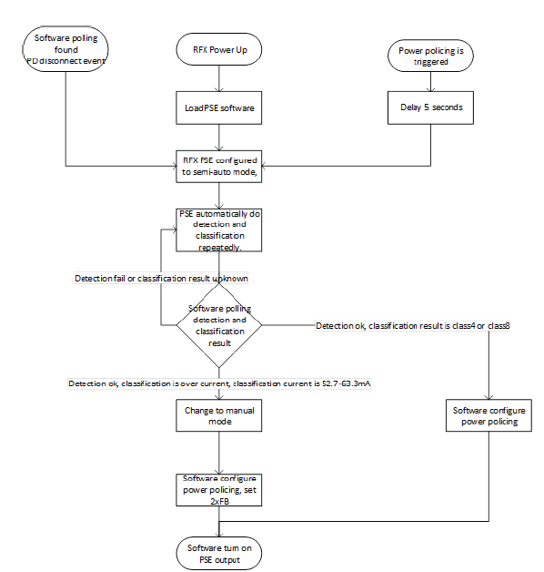
    A. when port current falls between 52.7~63.3mA,  it would recognized as Max Class 5

    B. Power                  

      ret = tps_SetDevice4PPowerAllocation(addr1,_4P_45W,_4P_45W);

    C. set the diagnostic mode:

                        ret = tps_SetDeviceOperatingMode (addr1, OPERATING_MODE_DIAGNOSTIC, OPERATING_MODE_DIAGNOSTIC,    OPERATING_MODE_OFF, OPERATING_MODE_OFF);


    D. Set the foldback mode:

                        ret = tps_SetPortILIM(s_sysChanNum, _2X_ILIM_FOLDBACK_CURVE);


    E. powering the channel:

                        ret = tps_SetPortPower_4P(s_sysChanNum, TPS_ON);


    F. Cycle detection of PowerEnable status,if it's enabled, set the power policing to 42.5W

                        CurPseParm.powerPolic = 85;                       //42.5W * 2

                            tps_GetDevicePowerEnableStatus(addr1, &powerStatPEnabn);

                            powerStatPEnabn = powerStatPEnabn & (PE1_STATUS + PE2_STATUS);

                            if(0 != powerStatPEnabn)                          //Power on (0x33)

                            {

                                osDelay(100);

                                ret = tps_SetPort4PPolicing(s_sysChanNum, (uint8_t)(CurPseParm.powerPolic));

    }

    End customer's requirement:

    Thanks a lot.

    Oliver Ou

  • Hi Oliver,

    Can you ask customer to read 2P PCUT and 4P PCUT register  value after the port is on? I am wondering if the correct value is set these registers.

    Best regards,

    Penny

  • Hi Penny,

    The register value:

    $ pseread 0x2d
    PSE Read REG[0x2d] = 0x0d

    $ pseread 0x21
    PSE Read REG[0x21] = 0xff

    $ pseread 0x2a
    PSE Read REG[0x2a] = 0x55

    $ pseread 0x2b
    PSE Read REG[0x2b] = 0xff

    The value of register  21h is 0x55.  PCUT = (N × PCSTEP).  0x55 * 0.5 = 42.5W

  • Hi ,

    Which port did you connect the Maxim class 5 PD to?

    From your register setting, you set channel 1 and channel 2 as a 4pair port, channel 3 an channel 4 as a 4 pair port. However, you set the channel 3&4's 4P PCUT to 0xff(register 0x2b) which is wrong. You will need to set it to 42.5W. 

    For 2P PCUT(0x1E to 0x21), you can set it to a little bit higher to 1/2 of the total max power. For example, if you want to limit the 4 pair port at 45W, you can set the 4P PCUT to 45W and 2P PCUT to 30W to consider the cable unbalance. Thanks.

    Best regards,

    Penny

  • Hi penny,

       In Maxim Class 5 mode, the power policing is right when set the port to 2P.

    Best regards,

    bing.deng

  • Hi user6250642,

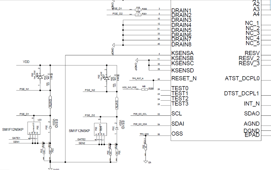
    In your code, you configure the ports to 4 pair ports, so I assume the hardware is design that way.If your hardware is designed in the way that the port is 4 pair port, you have to set the 4P PCUT. Can you share your schematic? Thanks.

    Best regards,

    Penny

  • The schematic:

  • Hi penny,

      I read out all the registers after I configured MAXIM Class5. The output is normal, but power policing is not right, the port would not shut down correctly

    PSE Read REG[0x00] = 0x1f
    PSE Read REG[0x01] = 0xff
    PSE Read REG[0x02] = 0x33
    PSE Read REG[0x03] = 0x33
    PSE Read REG[0x04] = 0x33
    PSE Read REG[0x05] = 0x33
    PSE Read REG[0x06] = 0x30
    PSE Read REG[0x07] = 0x30
    PSE Read REG[0x08] = 0x00
    PSE Read REG[0x09] = 0x00
    PSE Read REG[0x0a] = 0x00
    PSE Read REG[0x0b] = 0x00
    PSE Read REG[0x0c] = 0x74
    PSE Read REG[0x0d] = 0x74
    PSE Read REG[0x0e] = 0x00
    PSE Read REG[0x0f] = 0x00
    PSE Read REG[0x10] = 0x23
    PSE Read REG[0x11] = 0x08
    PSE Read REG[0x12] = 0x05
    PSE Read REG[0x13] = 0x0f
    PSE Read REG[0x14] = 0x22
    PSE Read REG[0x15] = 0x00
    PSE Read REG[0x16] = 0x00
    PSE Read REG[0x17] = 0x80
    PSE Read REG[0x18] = 0x00
    PSE Read REG[0x19] = 0x00
    PSE Read REG[0x1a] = 0x00
    PSE Read REG[0x1b] = 0x55
    PSE Read REG[0x1c] = 0x01
    PSE Read REG[0x1d] = 0x00
    PSE Read REG[0x1e] = 0x69
    PSE Read REG[0x1f] = 0x69
    PSE Read REG[0x20] = 0x69
    PSE Read REG[0x21] = 0x69
    PSE Read REG[0x22] = 0x00
    PSE Read REG[0x23] = 0x00
    PSE Read REG[0x24] = 0x00
    PSE Read REG[0x25] = 0x00
    PSE Read REG[0x26] = 0xe4
    PSE Read REG[0x27] = 0x00
    PSE Read REG[0x28] = 0x00
    PSE Read REG[0x29] = 0xff
    PSE Read REG[0x2a] = 0x55
    PSE Read REG[0x2b] = 0xff
    PSE Read REG[0x2c] = 0x86
    PSE Read REG[0x2d] = 0x0d
    PSE Read REG[0x2e] = 0x82
    PSE Read REG[0x2f] = 0x38
    PSE Read REG[0x30] = 0x00
    PSE Read REG[0x31] = 0x00
    PSE Read REG[0x32] = 0x00
    PSE Read REG[0x33] = 0x00
    PSE Read REG[0x34] = 0x37
    PSE Read REG[0x35] = 0x23
    PSE Read REG[0x36] = 0x6f
    PSE Read REG[0x37] = 0x38
    PSE Read REG[0x38] = 0x00
    PSE Read REG[0x39] = 0x00
    PSE Read REG[0x3a] = 0x00
    PSE Read REG[0x3b] = 0x00
    PSE Read REG[0x3c] = 0x00
    PSE Read REG[0x3d] = 0x00
    PSE Read REG[0x3e] = 0x00
    PSE Read REG[0x3f] = 0x00
    PSE Read REG[0x40] = 0x30
    PSE Read REG[0x41] = 0x01
    PSE Read REG[0x42] = 0x17
    PSE Read REG[0x43] = 0x21
    PSE Read REG[0x44] = 0x7f
    PSE Read REG[0x45] = 0x7f
    PSE Read REG[0x46] = 0x00
    PSE Read REG[0x47] = 0x00
    PSE Read REG[0x48] = 0x00
    PSE Read REG[0x49] = 0x00
    PSE Read REG[0x4a] = 0x00
    PSE Read REG[0x4b] = 0x00
    PSE Read REG[0x4c] = 0x00
    PSE Read REG[0x4d] = 0x00
    PSE Read REG[0x4e] = 0x00
    PSE Read REG[0x4f] = 0x00
    PSE Read REG[0x50] = 0x00
    PSE Read REG[0x51] = 0x00
    PSE Read REG[0x52] = 0x00
    PSE Read REG[0x53] = 0x00
    PSE Read REG[0x54] = 0x00
    PSE Read REG[0x55] = 0x00
    PSE Read REG[0x56] = 0x00
    PSE Read REG[0x57] = 0x00
    PSE Read REG[0x58] = 0x00
    PSE Read REG[0x59] = 0x00
    PSE Read REG[0x5a] = 0x00
    PSE Read REG[0x5b] = 0x00
    PSE Read REG[0x5c] = 0x00
    PSE Read REG[0x5d] = 0x00
    PSE Read REG[0x5e] = 0x00
    PSE Read REG[0x5f] = 0x00
    PSE Read REG[0x60] = 0x08
    PSE Read REG[0x61] = 0x00
    PSE Read REG[0x62] = 0x00
    PSE Read REG[0x63] = 0x80
    PSE Read REG[0x64] = 0x00
    PSE Read REG[0x65] = 0x00
    PSE Read REG[0x66] = 0x00
    PSE Read REG[0x67] = 0x00
    PSE Read REG[0x68] = 0x00
    PSE Read REG[0x69] = 0x00
    PSE Read REG[0x6a] = 0x00
    PSE Read REG[0x6b] = 0x00
    PSE Read REG[0x6c] = 0x00
    PSE Read REG[0x6d] = 0x00
    PSE Read REG[0x6e] = 0x00
    PSE Read REG[0x6f] = 0x00

    Best regards,

    bing.deng

  • Hi Bing,

    From power good bits in register 0x10, only channel 2 is turned on. Can you measure channel 1 and channel 2's drain voltage to verify the port status? The 2P PCUT (0x1E and 0x1F) is set to 0x67 which is 51.5W. In your test, what's the actual overload level when connecting to nonstandard max 5 PD? Thanks.

    Best regards,

    Penny

  • User6250642, It has been 3 weeks since we last heard from you. As such, I am going to close this thread and assume things are resolved.  If that is not correct, simply reply and the thread will reopen.

    Thanks,