Other Parts Discussed in Thread: , TPS23882
Hi sir
we want to use TPS23861 design as output power 6W, above questions need you help check it,tks!
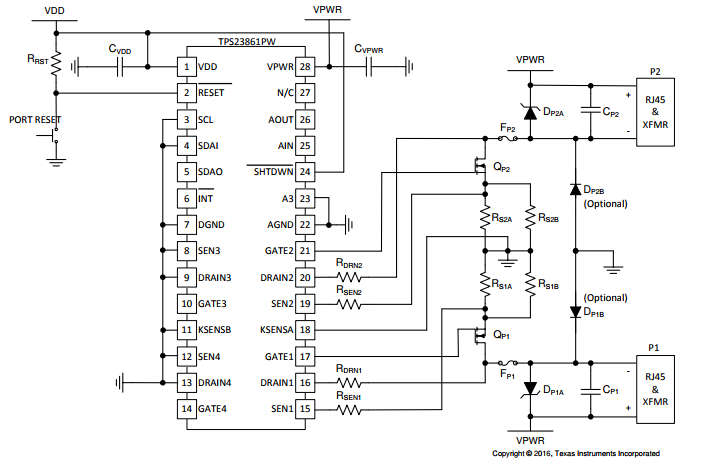
1.how the TPS23861 work mechanism?
2.that's the function of SDAI and SDAO, if use I2C,which PIN is need to connect?SCL and SDAI or SCL and SDAO,becuase from the schematic, the SDAO is not be used
3.we only need output power 6W, how to Configuration,pls help provide the way how to complete it
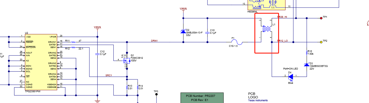
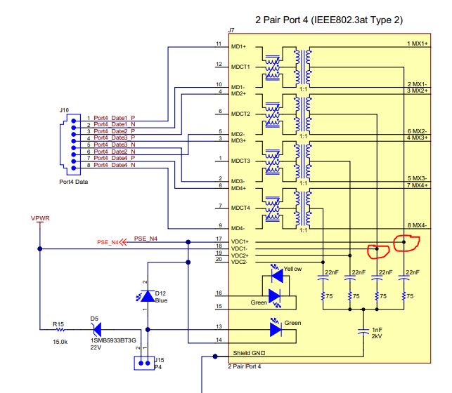
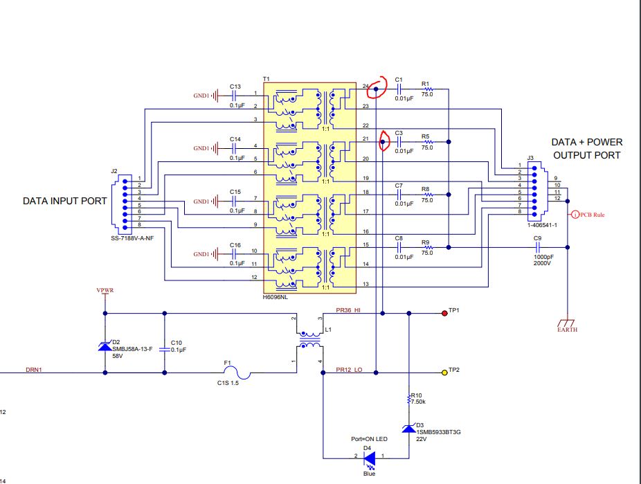
4.the datasheet recommend the schematic as the first Figure is connect to PHY port direct is not conncet to port by common mode inductor as the second figure, what's the functions of Common mode inductor?
5.from the schematic can be know the VPWR 48V is connect to the PHY port, so how the TPS23861 control its disconnet?could you help to descible this issue comprehensively,tks!