A related question is a question created from another question. When the related question is created, it will be automatically linked to the original question.
If you have a related question, please click the "Ask a related question" button in the top right corner. The newly created question will be automatically linked to this question.
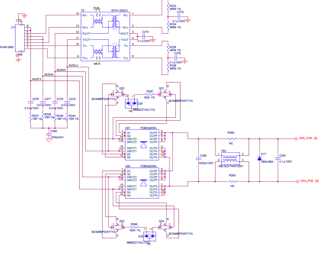
I don't see any issues with the schematic. Can you check the detection resistor is correct on the PCB with an ohm meter? Otherwise, the issue can be before the PD controller. Do you have schematic of the RJ45, bridge etc?
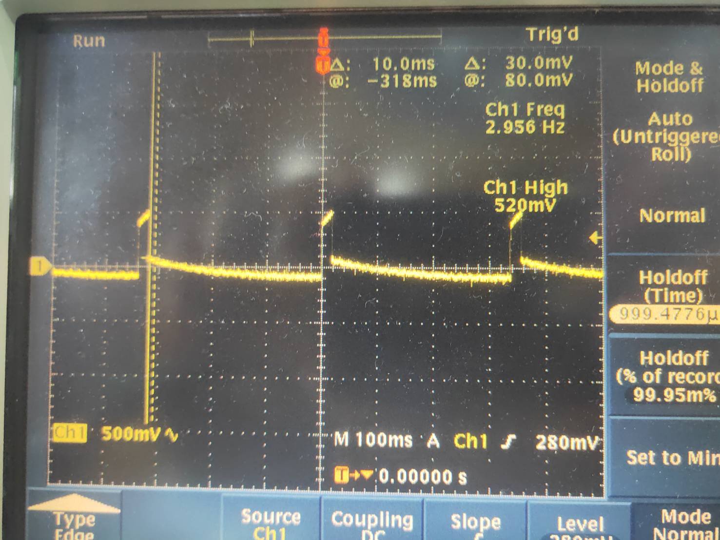
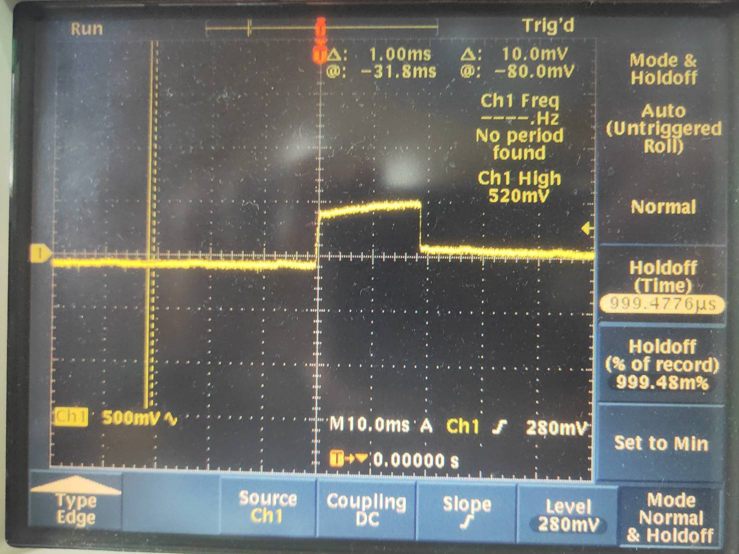
The only thing that catches my eye is the bob smith termination is connected to RTN. Can you try C282 and checking if this fixes the issue? Other than that, it could be FET bridge. If the C282 doesn't fix the issue, can you take a waveform of VDD-VSS at the IC (after the bridge) when you plug in the PSE?
Note also APD on the IC needs to be pulled down to RTN and not VSS. Can you also make this change on your board by unpopulating R293 and using a wire to short APD trace to RTN?
Please remove C282 so that it is not populated. Also, when you short APD to RTN, did you remove APD resistor to VSS?
You need to check the PCB, to help narrow down where in the PCB is the issue, you need to put a bench power supply voltage of 10V directly on VDD-VSS and measure the current with a current meter. The current should be ~400uA. If not, then there is an issue in the circuitry referenced to VSS.
If it is ~400uA, then you need to move the 10V to before the bridge directly on PAIRS12 and PAIRS36, it should be ~400uA. If not, then there is an issue on PAIRS12/36circuitry. Then do the same on PAIRS45/78. It should be ~400uA, if not, then there is an issue on PAIR45/78. If not ~400uA on all four pairs, then it is probably the FET bridge and you need to debug the FDMQ8205A and its circuit.
As suspected, this suggests the internal pass FET is being shorted. It is either by the PCB itself or the IC is damaged somehow. When there is 10V on VDD-VSS, the pass FET should be off so there shouldn't be 10V between VDD-RTN.
If you replace the IC with a new one, and the issue still occurs then there must be a short on your PCB. Note I didn't see an issue with your schematic but you may want to visually inspect and use an ohm meter to help narrow down where the short is.
256 ohms is not correct. It should be higher impedance (open circuit) when VDD-VSS is 10V. Also VDD-RTN should NOT be 10V.
Can you remove the IC, then measure on the PCB on the VSS and RTN plane what the resistance is? If it is not open circuit, then there is a short on the PCB that is connecting VSS and RTN when it shouldn't be. If it is open circuit then you can replace the IC with a new one to see if it fixes the issue.